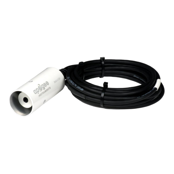
Apogee Instruments SI-400 Series Manuel du propriétaire - Page 6
Parcourez en ligne ou téléchargez le pdf Manuel du propriétaire pour {nom_de_la_catégorie} Apogee Instruments SI-400 Series. Apogee Instruments SI-400 Series 20 pages. Infrared radiometer

SPECIFICATIONS
Approximate Sensitivity
Output from Thermopile
Output from Thermistor
Input Voltage Requirement
Calibration Uncertainty (-30 to 65 C),
when target and detector temperature are
within 20 C
Calibration Uncertainty (-40 to 80 C),
when target and detector temperate are
different by more than 20 C
(see Calibration Traceability below)
Measurement Repeatability
Stability (Long-term Drift)
Response Time
Field of View
Spectral Range
Operating Environment
Dimensions
Mass
Cable
Calibration Traceability
Apogee SI series infrared radiometers are calibrated to the temperature of a custom blackbody cone held at
multiple fixed temperatures over a range of radiometer (detector/sensor body) temperatures. The temperature of
the blackbody cone is measured with replicate precision thermistors thermally bonded to the cone surface. The
precision thermistors are calibrated for absolute temperature measurement against a platinum resistance
thermometer (PRT) in a constant temperature bath. The PRT calibration is directly traceable to the NIST.
SI-111-SS
60 µV per C difference
difference between
between target and
target and detector
detector temperature
temperature
Approximately -3.3 to
Approximately -2.2
3.3 mV for a
to 2.2 mV for a
temperature
temperature
difference from -55 to
difference from -55
55 C
0 to 2500 mV (typical, depends on input voltage)
2500 mV excitation (typical, other voltages can be used)
0.2 C
0.5 C
Less than 2 % change in slope per year when germanium filter is maintained in a clean
condition (see Maintenance and Recalibration section below)
0.6 s, time for detector signal to reach 95 % following a step change
22° half angle
18° half angle
8 to 14 µm; atmospheric window (see Spectral Response below)
-50 to 80 C; 0 to 100 % relative humidity (non-condensing)
5 m of four conductor, shielded, twisted-pair wire; TPR jacket (high water resistance, high UV
stability, flexibility in cold conditions); pigtail lead wires; stainless steel (316), M8 connector
SI-121-SS
SI-131-SS
40 µV per C
20 µV per C
difference between
target and detector
temperature
Approximately -1.1
to 1.1 mV for a
temperature
difference from -55
to 55 C
to 55 C
0.2 C
0.3 C
0.5 C
0.6 C
Less than 0.05 C
14° half angle
23 mm diameter, 60 mm length
190 g (with 5m of lead wire)
located 25 cm from sensor head
SI-1H1-SS
40 µV per C
difference between
target and detector
temperature
Approximately -2.2
to 2.2 mV for a
temperature
difference from -55
to 55 C
0.2 C
0.5 C
32° horizontal half
angle; 13° vertical
half angle
