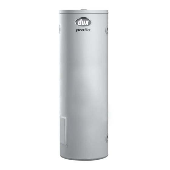
Dux ProFlo 315T236 Manuel du propriétaire - Page 5
Parcourez en ligne ou téléchargez le pdf Manuel du propriétaire pour {nom_de_la_catégorie} Dux ProFlo 315T236. Dux ProFlo 315T236 16 pages. Electric storage water heaters
Également pour Dux ProFlo 315T236 : Manuel du propriétaire (16 pages), Manuel du propriétaire (16 pages)

Owner's Manual – Proflo Electric Storage Water Heaters
Plumbing Connections
Water Supply:
This water heater has been manufactured
to suit the water conditions of most
Australian metropolitan supplies.
Please note certain water supplies can
have a detrimental effect on the water
heater and its life expectancy. If you are
unsure about the water supply you can
obtain information from the local water
supply authority.
The water heater is designed for use in
areas where the Total Dissolved Solids
(TDS) content of the water supply is less
than 2500 mg/L. The Tank Failure Warranty
does not apply in areas where the TDS
exceeds 2500 mg/L.
In areas where the TDS exceeds 600 mg/L,
it is possible the magnesium alloy anode
(supplied in standard water heaters) may
become over-reactive. To alleviate this, a
hard water model is recommended, or
the magnesium alloy anode should be
replaced with an aluminium alloy anode.
Aluminium alloy anodes are available from
your local Dux Supplier.
Water can also be very corrosive, the
measure of this is the saturation index. If
the water saturation index is greater than
0.40, an expansion control valve should
be fitted. If the index is greater than 0.80,
the electrical heating element should be
replaced with a low power density Incoloy
heating element. Please consult Dux After
Sales and Service for advice if required.
H0421
0421
Rev. N
Cold Water Connection:
The water heater is intended to be
permanently connected to the water supply
main, and not connected by a hose-set.
An approved isolating valve, non-return
valve, line strainer (optional but
recommended) and union must be fitted
between the water supply main and either
of the RP¾"(DN20) sockets marked
"INLET" at the bottom of the water heater.
See the diagram on page 5 for details.
All fittings must be approved by the
relevant Authority. Plastic pipes or fittings
shall not be used between the isolating
valve and the inlet.
The unused socket marked "INLET" is to be
plugged with one of the brass plugs supplied
inside the electrical cover of the water heater.
Ensure that a sealing material is applied to
the brass plug to prevent water leaks.
Water Supply Pressure:
This water heater is designed for direct
connection to water supply pressures of
up to 1,120 kPa for 80L, 125L and 160L
models, and 800 kPa for all other models.
Where the mains pressure can exceed or
fluctuate beyond this pressure, a pressure
reducing valve must be fitted in the cold
water inlet supply.
Note for New Zealand, South Australia
and Western Australia:
It is a requirement in these locations that
an expansion control valve be fitted on
the cold water supply line between the
non-return valve and the water heater.
3
