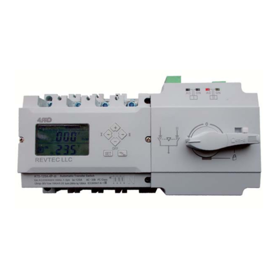
4PRO 250A-4P-di Manuel de démarrage rapide - Page 6
Parcourez en ligne ou téléchargez le pdf Manuel de démarrage rapide pour {nom_de_la_catégorie} 4PRO 250A-4P-di. 4PRO 250A-4P-di 7 pages. Automatic transfer switch

Working Conditions
Ambient temperature: -5
Atmospheric conditions
.
lower temperatures
It should take special treatment for the occasionally condensation due to the temperature variation
:
Altitude
Not more than 2000m
:
Pollution Class
The installation site environment pollution Class 3
:
-
Use category
AC 33iB
EMC Compatibility
:
General requirement
B class
:
Transmit Test
- Radio Frequency Transmission Test
- Radio-frequency radiation Transmit test: as per EN55011
Anti-interference Test
- Static Discharge: air discharge class 4; contact discharge class 3 as per IEC61000-4-2
- Radio-frequency electromagnetic field: Class 3 as per IEC61000-4-3 and IEC61000-4-6
- Fast transient pulse group: Class 4 as per IEC61000-4-4
- Surge: Class 4 as per IEC61000-4-5
- Short time voltage drop and voltage off: passed
Standards conformity
IEC60947-1(2001) (Low voltage switchgear and control gear, part one: General Rules)
IEC60947-3(2005) (Low voltage switchgear and control gear, switch, isolator and combined fuse switch etc)
IEC60947-6-1 (2005) (Low voltage switchgear and control gear multi-function switch: auto transfer switch etc. )
GB/T14048.1-2006 (Low voltage switchgear and control gear, part one: General Rules)
GB14048.3-2008 (Low voltage switchgear and control gear, switch, isolator and combined fuse switch etc)
GB14048.11-2008 (Low voltage switchgear and control gear multi-function switch: auto transfer switch etc. )
Transportation and Storage Conditions
During the transportation should not be exposed to rain and snow
Storage ambient temperature should between
Relative humidity - not more than 95
Common faults and troubleshooting
Fault Condition
Controller display does not
work after power is turned ON
Controller display shows
missed phase(s)
Controller display works,
but ATS does not work
Installation, Usage and Maintenance
This device requires professional installation and maintenance.
Product wiring should be done strictly as per input wiring mark.
The device must be reliable earthed to avoid any injuries, fire, explosions and equimpent damage.
Voltmeter must be used to check that the power sources are disconnected before installation.
Periodically make normal inspection
normally.
Periodically make a maintenance
℃- +
℃;
40
24 hours average - not more than
:
humidity not more than 50
(
)
common use
:
as per EN55011
-
25
% (
under 25
Possible fault reasons
Bad contact of input terminals
Controller Fuse Failure
Phase wire bad contact
Phase voltage is lower than
preset under-voltage value
Controller is in the OFF position
,
test manuall- and automatic transfer modes to insure that the device works
,
clear out the dust and check product insulation quality.
+
℃;
35
%
.+
.
at max
40'C. Max monthly humidity 90 . Higher humidity is allowed at
℃- +
℃
55
℃)
Ensure that input connections
are tighten and reliable
Replace the fuse
Fix the connection issue
Check the phase voltages
and change the preset value
Turn the switch to
a working position
%
Action
.
-
6
-
