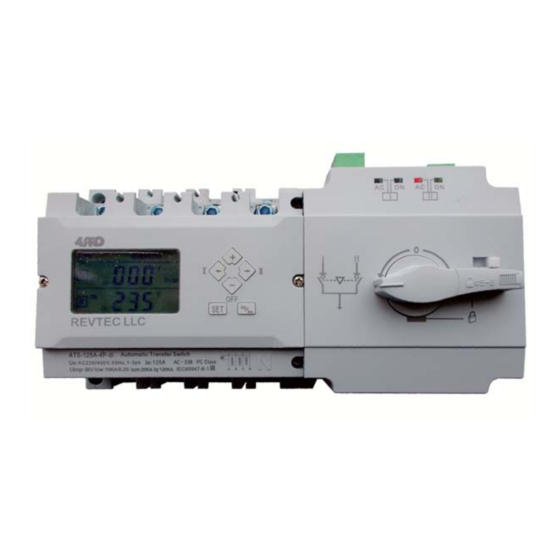
4PRO ATS-630A-4P-di Manuel de démarrage rapide - Page 5
Parcourez en ligne ou téléchargez le pdf Manuel de démarrage rapide pour {nom_de_la_catégorie} 4PRO ATS-630A-4P-di. 4PRO ATS-630A-4P-di 7 pages. Automatic transfer switch

Device connection
Normal Power
L1 L2 L3 N
L1 L2 L3 N
Load
4
Notes:
-
When the fire fighting equipment output signal is active (closed) it means that the Load circuits is powered by whether via Normal or
Reserve power source.
When the fire linkage inputs are active
To re-activate the device, the fire fighting signal must be removed and the Manual/Auto button must be pressed once. So, the ATS will
return to normal operation.
Reserve Power
L1 L2 L3 N
L1,L2,L3 - phase wire connections;
N - neutral wire connections.
Controller
,
the ATS will switch to OFF position disconnecting LOAD from power sources.
-
Controller
Display Controller
CONTROLLER TERMINAL CONNECTIONS
101 - 103 : Normal Power external Indicator
outputs ( Active AC230V 0.5A)
101 - Indicator common neutral line
102 - Normal power indicator signal output
103 - Normal power ON signal output
201 - 203 Reserve power external indicator
(
outputs Active AC230V 0 5A
201 - Indicator common neutral line
202 - Reserve power indicator signal output
203 - Reserve power ON signal output
301 - 302 Auxiliary power supply
301 - "+" input
302 - "-" input
401 - 404 Fire linkage control signal inputs and
feedback signal outputs
,
401 402 - Fire linkage signal passive inputs
,
403 404 - Feedback signal outputs (active when ATS
transfer is in OFF position)
501 - 503 - Generator remote start control signal
outputs
501 - Control signal NO point
502 - Control signal common point
503 - Control signal NC point
,
Normal Power
Normal Power ON
Reserve Power
Reserve Power ON
DC24V Aux. Power
Fire Linkage
Generator Control
/ .
)
15-
24VDC inputs
-
5
-
