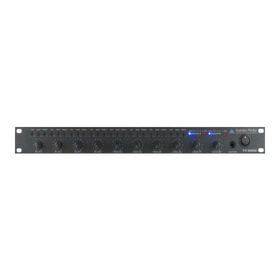
AUSTRALIAN MONITOR TX8202 Manuel d'utilisation - Page 6
Parcourez en ligne ou téléchargez le pdf Manuel d'utilisation pour {nom_de_la_catégorie} AUSTRALIAN MONITOR TX8202. AUSTRALIAN MONITOR TX8202 11 pages. 8 channel 1 ru mixer
Également pour AUSTRALIAN MONITOR TX8202 : Spécifications (2 pages), Spécifications (2 pages)

Internal Adjustments
Note: The following adjustments involve access to the inside of the TX8202 and should
only be attempted by a qualified technician. Always turn off the AC power and remove
the AC power cord before accessing the inside of the TX8202.
Tone Generator
There is a plug in option for a separate tone generator module.
VCA Control
There is a plug in option for a separate VCA module. You will need a module for each of the left and right
channels.
Master Left/Right Direct Out Assignment: A jumper labeled JP1 is provided for each of the first 4
channels. The jumpers are located near the front of the unit. When in the ON position, signal from that
channel is fed to both the master outputs and the direct outputs. When the switch is in the OFF position,
signal from that channel is fed to the direct line level output only. The pre or post assignment is set via a
jumper situated mid way towards the right on each channel labeled "Pre Post". This is used to make the
Direct Outputs either pre or post channel fader volume. Set to the rear the Direct Output is post fader (i.e.
the channel fader volume affects the Direct Output). Set to the forward position the Direct Output is pre
fader.
Mic/Line Switch for Channels 1-4: A four position dip switch is located on the main board behind each
input. To set a channel for microphone level, set switches 1 and 2 (MIC) to the ON position. To set a
channel for line level, set switches 1 and 2 to the OFF position. The unit ships from the factory set to mic
level.
Tone Generator to Direct Output Defeat Switch: Signal from the tone generator can be removed from
each direct output via switch # 4 (TG) on the internal dip switch per channel. When in the ON position, the
tones (when activated) are fed to the corresponding direct output as well as the master Left/Right outputs.
When the switch #4 is set to the OFF position, the tones are only present at the Master Left/Right outputs.
Phantom Power Defeat: Each of the XLR inputs has access to +15v DC phantom power. Phantom power
is selected via switch # 3 (PP) on the internal dip switches mentioned above. When switch # 3 is in the ON
position, +15v phantom power is available on the XLR input. Care should be taken to disable phantom
power before connecting any unbalanced or line source. The factory default position is with phantom power
set to the ON position.
Vox Muting Defeat: The muting function can be disabled by moving the jumper labeled JP2 (located
behind channel 8 volume control). In the ON position muting is disabled, in the OFF position muting is
enabled (go figure!). The unit ships from the factory with muting enabled, ie the jumper is set to the OFF
position. When channels 1 and 2 are removed from the main left/right output, the muting function is
automatically disabled.
