austriamicrosystems AS1351 Note d'application - Page 3
Parcourez en ligne ou téléchargez le pdf Note d'application pour {nom_de_la_catégorie} austriamicrosystems AS1351. austriamicrosystems AS1351 5 pages. Programming board

AS1351
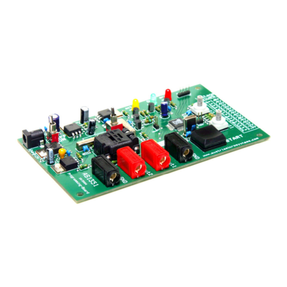
Programming Board Application Note
Voltage Selectors
Figure 3: Voltage Selectors
Starting Up
Introduction
The Programming Board can be used to program the AS1351 Dual LDO regulator. The IC will be programmed according to the setting of
the Rotary Switches. Programming is performed automatically after pressing the start button.
Power Setup
Make sure that the board is switched OFF (On/Off Switch "A" is OFF) then connect 12V supply voltage to the DC-jack
Input/Output
Description). The supply must be capable to drive a current of 900mA. The polarity of the DC-Jack connector must be +12V
inside and GND outside.
Inserting IC
The programming board must be equipped with the AS1351. When
inserting an IC into the socket it is vital that the Pin1 marker of the IC (small
dot) is placed in the corner where the socket is marked with the small dot.
Note: The programming board must be powered OFF while inserting or
extracting an IC from the socket.
Operational sequence
Measurement
1.
If not present get the datasheet for the AS1351 from www.austriamicrosystems.com. Drive the IC on the Programming Board
only with the recommended settings and values as described in the datasheet.
2.
Make sure that the board is turned OFF. (On/Off switch "A" set to OFF.) Connect the power supply if necessary.
Setup.)
3.
Insert an AS1351 into the socket. Pin1 must match with the pin1 marking on the socket.
4.
Set the power supply switch "B" to the desired supply voltage 3.3 or 5V
5.
Turn the programming board ON. (On/Off switch "A" set to ON.) The yellow LED "F" should be on now.
6.
Perform measurements at the outputs. "K-N"
Note: Due to influences of the socket the full performance of the regulators can be slightly lower. The AS1351 can be programmed to an
output voltage only once (One-Time-Programming OTP function).
www.austriamicrosystems.com
Table 4: Positions for Voltage Programming
Position
Voltage
0
1.8V
1
1.9V
2
2.0V
3
2.1V
4
2.2V
5
2.3V
6
2.4V
7
2.5V
Figure 4: Pin1 Marker
Revision 1.00
austriamicrosystems
Position
Voltage
8
2.6V
9
2.7V
A
2.8V
B
2.9V
C
3.0V
D
3.1V
E
3.2V
F
3.3V
(see Table 3:
(See Power
(See
Inserting
IC.)
3 - 4
