Bender B95 012 004 Manuel - Page 2
Parcourez en ligne ou téléchargez le pdf Manuel pour {nom_de_la_catégorie} Bender B95 012 004. Bender B95 012 004 20 pages. Control and indicating device for ems and eds systems
PRC470, PRC470E
oder nicht.
Löschen aller Alarmmeldungen
Zusätzliche Funktionen im RCMS-System:
Einstellung der individuellen Ansprechwerte für jeden
Kanal
Einstellung einer Vorwarnstufe zwischen 10 und 100 % des
Ansprechwertes
Einstellung eines Faktors
Anzeige der aktuellen Istwerte des Differenzstromes
Anzeige der Messstromwandlerabgänge, in denen der
Ansprechwert des Differenzstromes überschritten wurde
und Anzeige des entsprechenden Differenzstromes
Zusätzliche Funktionen im EDS-System
Einstellung des Wandlertyps (geschlossen oder teilbar)
Anzeige von Abgängen mit Isolationsfehlern
Manuelles Starten und Stoppen der Isolationsfehlersuche
Einstellung einer Messzeitverlängerung
Mit dem PRC470 kann der gesamte Anlagenbereich von einer
zentralen Stelle aus überwacht und gesteuert werden.
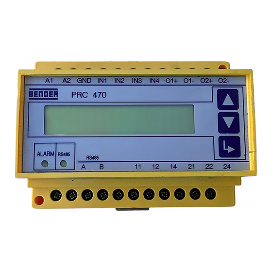
Bedienelemente
Abb. 1: Bedienelemente
Legende der Bedienelemente
1
Alarm-LED leuchtet, wenn ein Ansprechwert an einem der angeschlosse-
nen Auswertegeräte über- oder unterschritten wird (Sammelalarm).
2
RS485-LED zeigt Aktivitäten auf dem BMS-Bus.
3
Bedientasten UP, DOWN, ENTER
Montage und Anschluss
Stellen Sie vor Einbau des Gerätes und vor Arbei-
ten an den Anschlüssen des Gerätes sicher, dass
die Anlage spannungsfrei ist.
Wird dies nicht beachtet, so besteht für das Perso-
nal die Gefahr eines elektrischen Schlages.
Außerdem drohen Sachschäden an der elektri-
schen Anlage und die Zerstörung des Gerätes.
Montage
Das Gerät ist für folgende Einbauarten geeignet:
Installationsverteiler nach DIN 43 871 oder
Schnellmontage auf Hutprofilschiene nach
IEC60715:1995-10
oder Schraubmontage.
2
Additional functions in the RCMS system:
Additional functions in the EDS system
The PRC470 is capable of controlling and monitoring the entire
system from a central location.
Operating elements
A1
A2 GND IN1 IN2 IN3
IN4 O1+ O1- O2+ O2-
PRC470
V. 2.x
ALARM
RS485
RS485
A
B
11
1
2
Legende of operating elements
Installation and connection
Installation
The device is suitable for:
RCMS470-12 or EDS47x-12 .
Deleting all alarm signals
Setting the individual response values for each channel
Setting the prewarning level at between 10 and 100 % of
the response value
Setting a factor
Indication of the current act. value of the residual current
Indication of the measuring current transformer subcir-
cuits in which the response value of the residual current
has been exceeded and indication of the corresponding
residual current
Setting the transformer type (closed or separable)
Indication of subcircuits with insulation faults
Manual starting and stopping of insulation fault location
Setting an extension of the measuring time
12
14
21
22
24
Figure 1: Operating elements
1
Alarm LED lights up when the residual current in the connected evaluators
exceeds or falls below the set response value (common alarm).
2
RS485 LED indicates activity on the BMS bus.
3
Control keys UP, DOWN, ENTER
Make sure that the system is off circuit prior to in-
stallation and before commencing work on the
connecting cables.
Failure to do so exposes the personnel to the dan-
ger of electric shock.
In addition, the electrical installation could be
damaged and the device destroyed.
mounting into standard distribution panels according to
DIN 43 871 or
DIN rail mounting in compliance with IEC60715:1995-10 or
screw fixing.
3
108001 / 11.2004