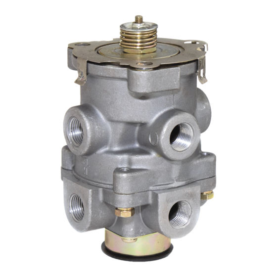
BENDIX E-10 Service Data - Page 4
Parcourez en ligne ou téléchargez le pdf Service Data pour {nom_de_la_catégorie} BENDIX E-10. BENDIX E-10 6 pages. Dual brake valves

SERVICE CHECKS
OPERATING CHECK
Check the delivery pressure of both primary and secondary
circuits using accurate test gauges. Depress the treadle
to several positions between the fully released and fully
applied positions, and check the delivered pressure on the
test gauges to see that it varies equally and proportionately
with the movement of the brake pedal.
After a full application is released, the reading on the test
gauges should fall off to zero promptly. It should be noted
that the primary and secondary delivery pressures may
vary by up to 5 psi for standard valves or up to 7.5 psi for
high differential valves with both supply reservoirs at the
same pressure. This is normal for this valve.
Important: A change in vehicle braking characteristics or
a low pressure warning may indicate a malfunction in one
or the other brake circuit, and although the vehicle air
brake system may continue to function, the vehicle should
not be operated until the necessary repairs have been
made and both braking circuits, including the pneumatic
and mechanical devices, are operating normally. Always
check the vehicle brake system for proper operation after
performing brake work and before returning the vehicle
to service.
LEAKAGE CHECK
1. Make and hold a high pressure (80 psi) application.
2. Coat the exhaust port and body of the brake valve with
a soap solution.
3. Leakage permitted is a 1" bubble in 3 seconds. If the
brake valve does not function as described above or
leakage is excessive, it is recommended that it be
replaced with a new or remanufactured unit, or repaired
with genuine Bendix
®
Bendix
parts outlets.
REMOVAL
1. Check the vehicle wheels or park the vehicle by
mechanical means. Drain all air system reservoirs.
2. Identify and disconnect all supply and delivery lines at
the brake valve.
3. Remove the brake valve and treadle assembly from
the vehicle by removing the three cap screws on the
outer bolt circle of the mounting plate. The basic brake
valve alone can be removed by removing the three cap
screws on the inner bolt circle.
DISASSEMBLY
(Figures 3 and 4)
1. If the entire brake valve and treadle assembly was
removed from the vehicle, remove the three cap screws
securing the treadle assembly to the basic brake
valve.
4
®
parts available at authorized
2. Remove the screw (9) securing the exhaust diaphragm
(10) and washer (11) to the exhaust cover (12).
3. Remove the four screws that secure the exhaust cover
(12) to the lower body.
4. Remove the Secondary inlet and exhaust valve
assembly (13) from the lower body.
5. Remove the four hex head cap screws securing the
lower body to the upper body and separate the body
halves.
6. Remove the rubber seal ring (14) from the lower body.
®
®
BENDIX
E-6
BRAKE VALVE ONLY (Figure 3):
7. While applying thumb pressure to the primary piston, lift
out and up on the three lock tabs of the primary piston
retainer (15).
®
™
BENDIX
E-10
BRAKE VALVE ONLY (Figure 4):
8. A.
While depressing the spring seat (7), remove
retaining ring (8).
B.
Remove the spring seat and coil spring (5).
9. Using a 3/8" wrench, hold the lock nut (16) on the
threaded end of the stem (17) in the primary piston (2).
Insert a screwdriver in the exhaust passage through the
center of the valve and engage the slotted head of the
stem.
10. Remove lock nut (16), spring seat (18), stem spring
(19), primary piston (2), and primary piston return spring
(6). Remove o-ring (34).
11. Remove adapter (1). Remove o-ring (4) from adapter.
Caution: Before proceeding with the disassembly, refer
to Figure 4 and note that the lock nut and stem are used
to contain the primary piston return spring, stem spring
and the relay piston spring. The combined force of these
springs is approximately 50 pounds and care must be
taken when removing the lock nut as the spring forces
will be released. It is recommended that the primary
piston and relay piston be manually or mechanically
contained while the nut and stem are being removed.
®
®
BENDIX
E-6
BRAKE VALVE ONLY:
12. Using a screwdriver to restrain the stem, as in step
nine, remove the lock nut (16), spring seat (18) and
stem spring (19).
13. Remove the relay piston (20), relay piston spring
(21), primary piston and primary piston return spring
(23) from the upper body. Use care so as not to nick
seats.
®
Note: Certain E-6
brake valves do not have a relay
piston spring (21). If this spring is not found, do not
install a replacement.
14. On valves manufactured after October 7,1976, a small
washer (24) will be found in the cavity in the lower side
of the primary piston (22).
