GAC ESD5520 Manuel de démarrage rapide - Page 2
Parcourez en ligne ou téléchargez le pdf Manuel de démarrage rapide pour {nom_de_la_catégorie} GAC ESD5520. GAC ESD5520 8 pages. Speed control unit
3
INSTALLATION
reaD THIS enTIre GUIDe Before PerformInG an InSTaLLaTIon.
•
An overspeed shutdown device, independent of the governor system, should be used to prevent loss of
engine control which may cause personal injury or equipment damage.
•
Do not rely exclusively on the governor system electric actuator to prevent overspeed. A secondary shutoff
device, such as a fuel solenoid must be used.
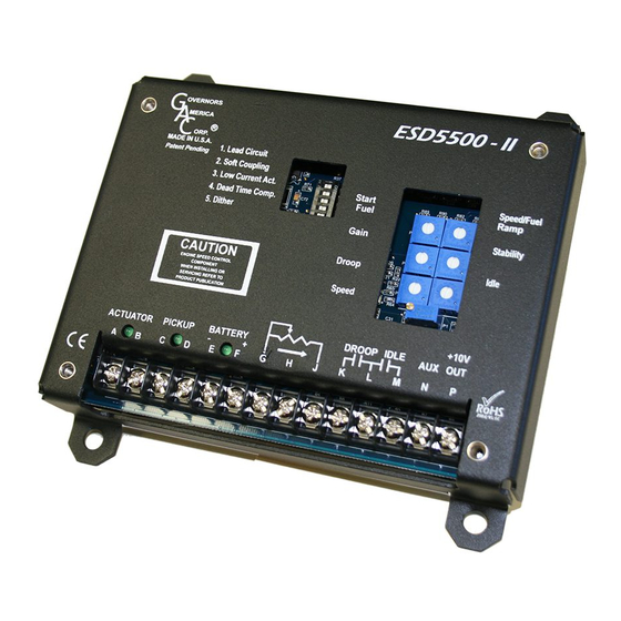
When wiring eSD5500-II Series controllers:
1.
Use shielded cable for all external connections to the eSD controller.
2.
One end of each shield, including the speed sensor shield, should be grounded to a single point on the ESD case.
3.
Terminal A, B, E,and F should be 16 AWG or larger. Long cables require increased wire size to minimize voltage drops.
4.
Magnetic speed sensors Terminals C and D must be twisted and or shielded for the entire length.
5.
The gap between the speed sensor and the ring gear teeth should be smaller than 0.02 in [0.5 mm] usually backing out 3/4 turn after
touching ring gear teeth. Speed sensor voltage should be at lease 1 V AC RMS during cranking.
6.
Terminal P is used to supply +10 V DC regulated supply to accessories. No more than 20 mA of current can be drawn from this supply.
Ground reference is Terminal G. A short circuit in this terminal can damage the speed control unit.
7.
Do not over-tighten terminals. Torque to no greater than 9.0 in-lb ±2.5 [1.01 ±0.28 N∙m].
Dimensions:
in
[mm]
ESD5500-II Fusion Series Speed Control Unit 1-2020-A4
2
Governors America Corp. © 2021 Copyright All Rights Reserved
Preferred vertical orienta-
tion allows for the draining
of fluids in moist environ-
ments.
Mount in a cabinet, en-
gine enclosure, or sealed
metal box.
Avoid Extreme Heat
PIB2180