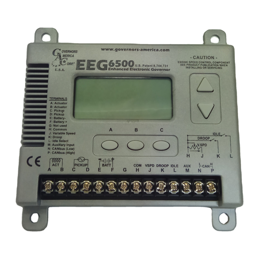
GAC EEG6500 Manuel - Page 4
Parcourez en ligne ou téléchargez le pdf Manuel pour {nom_de_la_catégorie} GAC EEG6500. GAC EEG6500 9 pages. Enhanced electronic governor with quikset display

8
ADJUSTING FOR STABILITY
Once the engine is running at operating speed and at no load, the following
governor performance adjustments can be made to increase engine stability.
GAIN - RATED SPEED & IDLE SPEED
The EEG6500 is equipped with two separate gains, one for rated
NOTE
speed, the other for idle speed. Both are set using the GAIN set-
ting on the Quikset menu.
GAIN TYPE
1.
Selected when IDLE input is disconnected.
RATED SPEED
1.
Connect the idle input to ground.
IDLE SPEED
2.
Change GAIN value.
3.
Disconnect Idle input from ground to switch back to Rated.
Idle icon will blink.
NOTE
PARAMETER
1.
Increase this parameter until instability develops.
2.
Then, gradually decrease this parameter until stability returns.
A.
GAIN
3.
Finally, decrease this parameter one increment further to ensure
stable performance.
4.
If instability persists, adjust the next parameter.
1.
Follow the same adjustment procedure as the GAIN parameter.
B.
STABILITY
2.
If instability persists, adjust the next parameter.
1.
If fast instability occurs, switch DEADTIME to low and repeat
C.
DEADTIME
steps A & B.
Normally, adjustments made at no load achieve satisfactory per-
NOTE
formance. For further performance, refer to sections (10) & (11).
10
ADVANCED PARAMETERS MENU
Display Special
Menu Parameters:
Selecting Parameters:
Adjust Parameters:
Return to Quikset Menu:
1. After 3 minutes of no user input, EEG switches to Quikset Menu.
NOTE
2. "Lock" is displayed when attempt to change a Read-Only
parameter.
EEG6500 - Variable Speed Response to External Voltage Input
Variable Speed Parameter (VSPD)- 'ON'
ADJUSTMENT PROCEDURE
QUIKSET MENU
ADJUSTMENT PROCEDURE
Hold ALL 3
until
"AUX" appears in display
Previous
Next
Parameter
Parameter
Increase
Parameter
Decrease
Parameter
Hold ALL 3
for 2 seconds
9
ADJUSTING FOR DROOP
After the initial set up is completed and the # of Teeth, Crank Termination
Speed and Rated Speed are set, position the external switch connecting
terminals 'H' and 'K' on to activate the DROOP mode following these sequence
steps.
1.
Go to the Advanced menu: Press and hold all three buttons simultaneous-
ly for two seconds to switch to Advanced Menu.
Confirm that the VSPD (Variable Speed / Fixed Speed Control) is off.
2.
Default position is off.
3.
Confirm that the LEAD circuit is off. Default position is ON.
4.
Set the NLCU (No Load Current) to the measured / displayed current
value when operating at no load rated speed (default value is 0.5 amps.)
5.
Set the FLCU (Full Load Current) to the measured / displayed current
value when operating at full load rated speed (default value is 4.0 amps.)
6.
Return to the Main Menu: Press and hold all three buttons simultaneously
for two seconds to switch to the Main Menu.
7.
Select and set DROOP to the desired percentage.
8.
Change the Speed parameter, which turns into the 'DROOP OFFSET'.
This sets the RPM, above operating speed, to which the system will be
commanded when DROOP is enabled. This is an offset value.
1500 RPM operating speed x 0.05 (5.0% droop) = 75 RPM
EXAMPLE
Input 75 RPM, this is the offset value.
The NLCU entered must be less than the FLCU and the differnece between
the two must be at least 0.5A. If an invalid combination is entered a warning
will be flagged and the parameters will be default to 0.5A and 4.0A.
ADVANCED MENU PARAMETERS (CONFIGURABLE)
Parameter
Auxiliary Input Enable
AUX
145 Hz/volt, 5 volt nominal Range: 1-9 V
Variable Speed or Trim Select
VSPD
(On=Variable Speed, Off=Trim)
LFG
Light Force Governor
Lead Circuit - For Increased Governor
LEAD
Response / Increased GAIN Adjustment
Authority.
No Load Current - Amps
NLCU
Full Load Current - Amps
FLCU
ADVANCED MENU PARAMETERS (READ ONLY)
Parameter
SREV
Software revision number
BID
Software build identifier
Assembly revision: Identifies board hardware configuration, not
AREV
software.
FLTH
Highest fault code since power up. Aids in trouble shooting.
Supplemental data associated with last fault code. Aides in trou-
DATL
bleshooting.
Last fault code detected. Associated data is DATL and aids in
FLTL
trouble shooting.
EEG6500 Enhanced Electronic Governor 05.09.18
4
Definition
Range
Off, On
Off, On
Off, On
Off, On
0.0 - 9.5
0.5 - 10.0
Definition
© 2018 Copyright All Rights Reserved
Default
Off
Off
Off
On
0.5
4.0
PIB 5010 F
