Gage Bilt GB2581 Manuel d'instructions original - Page 7
Parcourez en ligne ou téléchargez le pdf Manuel d'instructions original pour {nom_de_la_catégorie} Gage Bilt GB2581. Gage Bilt GB2581 15 pages. Installation tool
WARNING:
Only qualified and trained operators should install, adjust or use the assembly power tool for non-threaded
mechanical fasteners.
WARNING:
Operator
WARNING:
It is required that eye protection, hearing protection and safety boots be worn at all times while handling this
equipment.
WARNING:
The users or the user's employer should assess specific risks that could be present before each use based on
their application.
● Be sure there is adequate clearance for tool and operator's hands before proceeding. Keep fingers clear of
any moving parts. Keep fingers clear from fasteners and installed materials. Severe personal injury may result.
●
Verify the air lines and/or hydraulic hoses are not a trip hazard.
●
Ensure that there are no electrical cables, gas pipes, etc., which can cause a hazard if damaged by the tool
●
Verify that hydraulic hose fittings and couplings, air and electrical connections are secure before each use.
WARNING:
Do not pull rivet in the air. Personal injury from fastener ejecting may occur.
WARNING:
Do not carry from hoses or use as a hammer.
WARNING:
Do not use in explosive atmosphere.
WARNING:
Ensure air hose is securely connected to avoid possible hose whipping.
WARNING:
Always disconnect air supply, where applicable, when tool is not in use to prevent accidental start-up.
WARNING:
Do not exceed the maximum relief-valve setting stated on the tool and manual.
WARNING:
Do not operate when recommended pressures are exceeded as it could cause severe personal injury and or
damage the equipment.
WARNING:
Use only Gage Bilt hydraulic hoses and couplings, or equivalent, rated for 10,000 psi. (689.48 bar) working
pressure.
CAUTION:
Do not use beyond the design intent.
#1. Set hydraulic power unit to the recommended pressure, 7,400 psi (510.2 bar) Max. for the pull and 3,200 psi (220.6 bar) Max. for the
return. Gage Bilt (942280) pressure gage assy (sold separately) is recommended to aid in this procedure. "See hydraulic power unit
manual for correct procedure when adjusting pressures".
Note:
Power units require a free flow of air for cooling purposes and should therefore be positioned in a well ventilated area
free from hazardous fumes.
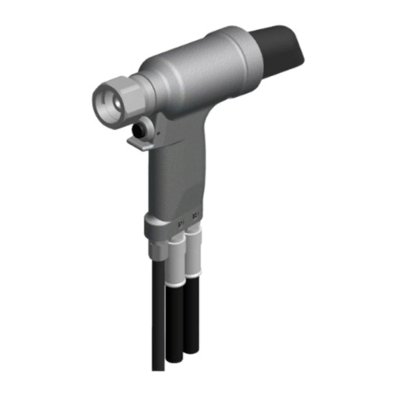
#2. Attach deflector (258032) to rear of barbed retainer (258015) located on rear of cylinder-machined (258009). Rotate deflector
(258032) away from operator and other persons working in the vicinity.
#3. Turn off the hydraulic power unit. Wipe all couplers clean before connecting. Failure to do so can result in damage to the couplers
and cause overheating. Connect hydraulic hoses then electric cord / air line to power supply.
#4. Turn hydraulic power unit on and cycle tool five times by depressing actuator to ensure piston assy (258111) is in the full
forward position.
#5. Disconnect hydraulic hoses (206119) and cord assy (480223) / air line (750154) from power supply .
#6. Select proper Nose Assembly. (See accessories pg.14).
#7. Hold piston assy (258111) in place using a 3/8" allen wrench in the back of the piston assy and screw collet securely on piston assy.
#8. Slide anvil over collet, slide retaining nut stop (480125) and retaining nut (480124) over anvil and tighten retaining nut (480124).
(See proper data sheet for further instructions.)
#9. Re-connect cord assy (480223) / air line (750154) and hydraulic hoses (206119) to power supply.
GB2581 S/N: 1068 AND ABOVE
PLEASE CONTACT GAGE BILT FOR ALL OTHER SERIAL NUMBERS.
HOW TO SET-UP THE GB2581 / GB2581A
MUST
read and understand all warnings and cautions.
7,400 psi
(510.2 bar)
Max.
for the pull
3,200 psi
(220.6 bar)
Max. for
the return
7
Images may not reflect actual
p.s.i. settings
.
Rev. 4/17