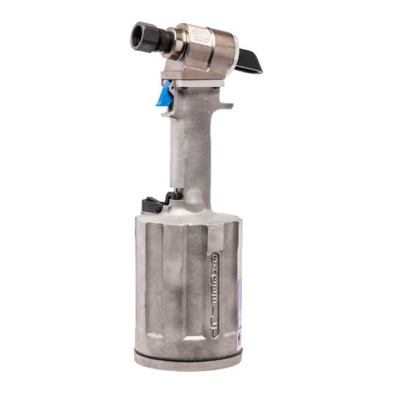
Gage Bilt GB756 Manuel - Page 12
Parcourez en ligne ou téléchargez le pdf Manuel pour {nom_de_la_catégorie} Gage Bilt GB756. Gage Bilt GB756 14 pages.

NOSE ASSEMBLIES
Nose assemblies are attached using a 1-1/4 inch socket on the rear of the piston ass'y. Socket (A-1307) may
be ordered separately from Gage Bilt. GB756TK tool repair kit may also be ordered separately which in-
cludes socket (A-1307) and other tools needed for complete tool overhaul.
When attaching offset and right angle nose assemblies an adapter and stroke limiter is necessary. Refer to
nose assembly selection chart on page 13 for the adapter and stroke limiter for your specific nose assembly.
Follow instructions below for installation of stroke limiter.
STROKE LIMITERS ARE DESIGNED FOR THE PROTECTION OF THE OPERATOR AND
EQUIPMENT. FAILURE TO OPERATE TOOL WITH STROKE LIMITER AS REQUIRED WILL
RESULT IN DAMAGE TO NOSE ASSEMBLY OR TOOL AND MAY RESULT IN PERSONAL
INJURY. IF UNSURE YOUR NOSE ASSEMBLY REQUIRES A STROKE LIMITER
1. Disconnect air supply from tool.
2. Remove rear bleeder screw (marked #2). CAUTION: Rear bleeder screw (marked #2) may be under
pressure.
3. Remove deflector (756120) and end cap (756116). CAUTION: Pour hydraulic fluid into a container.
4. Slide stroke limiter over rear piston ass'y (756211).
5. Tighten end cap onto head cylinder and re-attach deflector (756120) . See torque spec.
6. Attach air bleeder ass'y (704153) to rear hole.
7. With front button head screw (marked #1) and stat-o-seal tightened to 35-40 inch pounds, and the air
bleeder ass'y (704153) attached to rear hole (marked #2), connect tool to air with the pressure being set at
40-50 psi.
8. Cycle tool 10 times, holding actuator down for 5 seconds and releasing the actuator for 5 seconds.
9. Depress actuator and hold until piston ass'y (756211) is in its full rear position. While still holding actuator,
disconnect air supply.
10. Remove air bleeder ass'y (704153) and install rear button head screw (405482) and stat-o-seal (A-1115)
on head cylinder (756300) hole marked #2.
11. Refer to filling and bleeding instructions on page 5, step #7.
S/N: 1226 AND ABOVE
PLEASE CONTACT GAGE BILT FOR ALL OTHER SERIAL NUMBERS.
CONTACT GAGE BILT.
12
REV. 3/14
