Gage Bilt GB756 Manuel - Page 4
Parcourez en ligne ou téléchargez le pdf Manuel pour {nom_de_la_catégorie} Gage Bilt GB756. Gage Bilt GB756 14 pages.
PRINCIPLE OF OPERATION
When the actuator is depressed, the throttle valve is shifted, directing the pressurized air inside the tool to the
bottom of the air piston ass'y, moving it in an upward direction. The air above the air piston ass'y is then
directed out the exhaust, on the bottom of the tool. Simultaneously, the piston rod connected to the air
piston ass'y is also moving up, forcing hydraulic oil up and into the front of the head cylinder, causing the
piston ass'y to move to the rear of the head cylinder. The oil from the rear of the head cylinder is directed to
the bottom of the piston rod assembly, inside the handle. The internal components of the attached nose
assembly are also moving with the piston ass'y to start the fastener installation.
installation is completed the actuator is released allowing spring pressure to move the throttle valve to shift,
directing the air pressure to the top side of the air piston ass'y and reversing the sequence.
HOW TO USE THE GB756
WARNING:
OPERATOR
WARNING:
IT IS REQUIRED THAT EYE PROTECTION AND HEARING PROTECTION BE WORN DURING
OPERATION.
WARNING:
DO NOT PULL RIVET IN THE AIR. PERSONAL INJURY FROM FASTENER EJECTING MAY OCCUR.
WARNING:
AIR IS EXHAUSTED FROM THE BOTTOM OF THE TOOL. DIRECT BOTTOM OF THE TOOL
(EXHAUSTED AIR) AWAY FROM OPERATOR, OTHER PERSONS WORKING IN THE VICINITY,
FOREIGN MATTER AND LIQUID.
CAUTION:
DO NOT USE BEYOND THE DESIGN INTENT.
The tool is shipped with a plastic plug in the air inlet connector. The connector has a 1/4-18 female pipe thread to accept
end-user air hose fitting. The tool comes with oil and is ready to use.
1. Remove plastic shipping plug from Swivel (A-249) and screw in your air fitting.
2. Attach Deflector (756120) to rear of Head Cylinder (756300).
WARNING:
ROTATE DEFLECTOR AWAY FROM OPERATOR AND OTHER PERSONS WORKING IN THE VICINITY.
3. Connect tool to air hose with 90 psi. (3/8 minimum diameter air line is recommended). Cycle tool 5 times by
depressing and releasing actuator. (Clean dry air is mandatory).
WARNING:
ENSURE AIR HOSE IS SECURELY CONNECTED TO AVOID POSSIBLE HOSE WHIPPING.
4. Disconnect air hose from tool.
5. Select proper Nose Assembly, screw collet ass'y onto piston ass'y and slide anvil over collet, secure with retaining
nut stop (480125) and nut (480124). (See proper data sheet for further instructions.)
6. Connect air supply.
7. Insert rivet into Nose Assembly and the application then depress actuator. Upon releasing the actuator the stem will
eject to the rear of the tool.
S/N: 1226 AND ABOVE
PLEASE CONTACT GAGE BILT FOR ALL OTHER SERIAL NUMBERS.
MUST
READ AND UNDERSTAND ALL WARNINGS AND CAUTIONS.
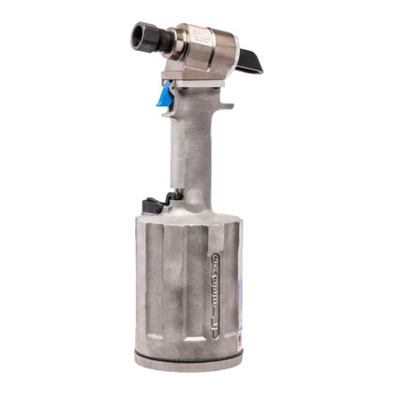
CYLINDER
HEAD
DEFLECTOR
RED
SHIPPING
PLUG
QUICK
DISCONNECT
FITTING
NOSE
ASSEMBLY
RIVET
WORK
TRIGGER
Image may not reflect actual tool
4
When the fastener
REV. 3/14