Hi-Force AHP1120б Series Manuel d'instruction - Page 3
Parcourez en ligne ou téléchargez le pdf Manuel d'instruction pour {nom_de_la_catégorie} Hi-Force AHP1120б Series. Hi-Force AHP1120б Series 8 pages. Air driven hydraulic pumps
INSTRUCTION MANUAL – AIR DRIVEN HYDRAULIC PUMPS:
Model Series: AHP1120, AHP1120R, AHP1121, AHP1121R, AHP1122, AHP1122R, AHP1141, AHP1142,
HAP21011, HAP21012, HAP21014, HAP21016, HAP21021, HAP21022, HAP21024, HAP21026, HAP21031,
HAP21032, HAP21034, HAP21036, HAP21041, HAP21042, HAP21044, HAP21046,
5.2.2 - Pump hydraulic connections Models
AHP1141/ AHP1142
Connect the hydraulic pressure hose to
the outlet port (Port A Fig 5) and the
reservoir port (Port B Fig 5), the hose
must be fitted with a 3/8" NPTF fitting
after binding the thread with Teflon
tape.
Use a slotted tip screwdriver to extract
the breather plug to the first click
(position D in Fig 8)
5.2.3 Pump hydraulic connections:
AHP1120R/AHP1121R/AHP1122R
Connect the hydraulic pressure hose to
(Port A Fig:14). The hose must be fitted
with a 3/8" NPTF fitting after binding the
thread with Teflon tape.
Unscrew the breather screw (Fig: 6) by
three or four turns using an appropriate
screwdriver.
5.3 Connecting the compressed air line.
Select a quick coupler that is
compatible with the air-line supply and
connect it to the air inlet connection
(Fig. 1)
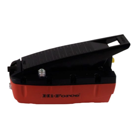
6: Operation
6.1 AHP1120/AHP1121/AHP1122.
To start the pump press down on the
treadle with your foot (Marked: PUMP
Fig. 14). This will make the pump deliver
pressurized oil to the connected
cylinder/tool.
When the treadle pedal is released the
pump will stop delivering oil but the
pressure/load in the system is
maintained.
Hi‐Force Limited – Prospect Way – Daventry – Northants NN11 8PL – United Kingdom
Tel: +44(0) 1327 301000: Fax: +44(0) 1327 706555: Website: www.hi‐force.com
To return the system pressure/load to
zero, press the treadle in the area
marked "RELEASE" (Fig: 15)
6.2 AHP1141 and AHP1142.
These units are fitted with 4/3 way directional
control valves for use with double acting
cylinders.
Position 1 (Fig11/a) - oil is sent to Port 'B' and
returns to the reservoir via Port 'A' (Fig 5)
Position 2 (Fig11/b) - locked position. Ports 'A'
and 'B' are closed and the Oil flow returns to
the reservoir.
Position 3 (Fig11/c) - oil is sent to Port 'A' and
returns to the reservoir via Port 'B'.
WARNING:
Immediately after the pump installation, the
circuit may contain air locks which prevent
pressurization. If
the
pump
pressurize the oil circuit, proceed as described
below.
The following operations are the only actions
which can be to the pump using the hands.
Under normal circumstances the must be used
by foot operation.
is
unable
to