Hi-Force MHP300 Manuel d'instruction - Page 2
Parcourez en ligne ou téléchargez le pdf Manuel d'instruction pour {nom_de_la_catégorie} Hi-Force MHP300. Hi-Force MHP300 3 pages. Hydrotest pump series
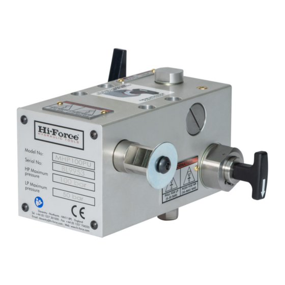
Major Pump Components
The above diagrams show where all the major
operating components of the MHP pumps are
located.
Operating Fluids:
The MHP pump is designed to operate
successfully with most hydraulic fluids, many
lubricating oils and water.
Some fluids may require specially fitted pump
seals. If in doubt please consult your Hi-Force
Distributor.
Preparation for Use:
1. Fill the reservoir with the chosen fluid, leaving
a small air space in the reservoir (1-2cm from
the top of the fluid to the filler plug.
2. MHP100 to MHP700 pumps the outlet port has
a 3/8" NPT thread. MHP1000 pumps, the outlet
port is 3/8" BSP. Only hoses with a 4:1 safety
rating on burst pressure may be used.
Hi-Force Limited – Prospect Way – Daventry – Northants NN11 8PL – United Kingdom
Tel: +44(0) 1327 301000: Fax: +44(0) 1327 706555: Website: www.hi-force.com
INSTRUCTION MANUAL:
Model Series: MHP100 –MHP1000 inclusive
Check hose for damage and connect it to the
pump. Always apply good quality thread
sealant or 11/2 turns of Teflon tape, taking care
NOT to allow loose ends of the tape to enter
the hydraulic system. Do not overtighten the
connections – it can lead to premature failure
or rupturing of fittings at below rated capacity.
Your Hi-Force Distributor can supply you with
the correct hoses for your pump.
3. Fit the operating lever to the pump using the
bolt and washer provided. The handle can be
fitted in many positions at 45 degree intervals.
Choose the most comfortable one for the
operator. Ensure the handle can be operated
through its entire travel range.
** A small amount of free movement of the
handle is normal and is due to the clearances
in the manufacturing processes of the working
parts of the pump. This free movement should
not be confused with loss of effective stroke
due to other causes.**
4. Occasionally the rocker shaft will need
greasing with a medium grade grease. This is
done by removing the back plate. With the
back plate off the rocker shaft can be
removed and grease applied to all surfaces.
Bleeding the System:
1. Open the release valve on the pump by
turning it anti-clockwise. Select low pressure by
pulling out the High/Low Pressure Changeover
switch. Now operate the pump through its
entire stroke slowly and smoothly at least 10
times. Stop pumping and push in the High/Low
Pressure Changeover Switch to obtain high
pressure. Again operate the pump through its
entire range slowly and smoothly at least 10
times. The pump should now be primed and
ready to use.
2. Close the Pressure Release Valve by turning
clockwise using hand pressure ONLY. Do NOT
over tighten!
Select low pressure and operate the pump
lever. When using the pump in a hydraulic
circuit or for pressure tests it may be necessary
to vent air from the circuit at the highest point
in the system. When using the pump with a
hydraulic cylinder, fully extend the cylinder,
then invert the cylinder (plunger end down)
and open the release valve on the pump to
return any air in the system to the reservoir.
Repeat bleeding operations if necessary.
Operation:
1. Start the pumping operation in low pressure
to obtain rapid advance to load. When the
operating effort reaches 52 Bars or the operator
effort becomes excessive, select High Pressure
by pushing in the pressure changeover button.