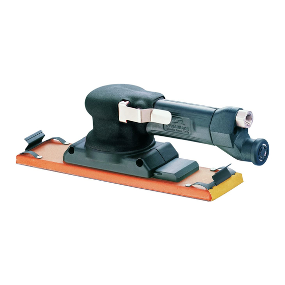
Dynabrade 51350 Instructions importantes concernant l'utilisation, l'entretien et la sécurité - Page 3
Parcourez en ligne ou téléchargez le pdf Instructions importantes concernant l'utilisation, l'entretien et la sécurité pour {nom_de_la_catégorie} Dynabrade 51350. Dynabrade 51350 4 pages. Dynaline file board sander

Disassembly/Assembly Instructions –
Important: Manufacturers warranty is void if tool is disassembled before warranty expires.
A complete Tune-Up Kit , (P/N 96531), is available which includes assorted parts to maintain motor in tip-top shape. A Motor Repair Kit (P/N 96046) is
available which contains special tools for disassembly/assembly of machine.
Gearbox Disassembly:
1. Disconnect tool from power source.
2. Invert machine and secure in vice, using 57092 Collar (Supplied in 96046 Repair Kit) or padded jaw.
3. Disconnect sanding pad by removing 95885 Screws (2) with a 3 mm wrench.
4. Remove gearbox assembly by removing 95642 Screws (2) and 95641 Hex Nuts with a phillips head screw driver.
5. Carefully separate 57427 Gearbox Halves. Remove one gearbox half, making sure no parts fall to the ground.
6. Remove and set aside the 57433 Slide-Board on non-vacuum models (57432 on vacuum models), 57431 Transfer Pinion (2), 57438 Counterweight
Assembly, 57445 Needle Bearing and the other 57427 Gearbox half.
7. Clean grease off old dirty components and inspect for damaged parts.
Motor Disassembly:
1. Insert 56058 Lock Ring Wrench (Supplied in 96046 Repair Kit) into corresponding tabs of lock ring and unscrew. Pull with a side to side action to
remove motor from housing. Motor may now be serviced.
2. Remove 54467 Retaining Ring/Planetary Gear Assembly using (2) 50679 26 mm wrenches (Supplied in 96046 Repair Kit). Set aside.
Note: See Planetary Gear Disassembly.
3. Remove 57056 Rear Plate by holding onto 51354 Cylinder and pressing 54470 Rotor Pinion out of 01206 Bearing.
4. Remove 54491 Blade (5), rotor set and 56047 Rotor Key.
5. Disassemble 57437 Front Plate by pressing 54470 Rotor Pinion through front plate. Note: One 01139 Bearing will remain on rotor pinion. To remove
press pinion through remaining bearing.
6. Press 01206 Rear Bearing from 57056 Bearing Plate.
Planetary Gear Disassembly:
1. Insert 54470 Rotor Pinion into the center of the planetary gear assembly. Install the 56047 Rotor Key into
the key way of the rotor pinion, and hold the rotor pinion in a soft aluminum or bronze jaw vice.
2. Place a 26 mm wrench on the flats of the 54467 Retaining Ring and an adjustable 3 mm pin spanner
wrench into the two empty holes on the 57430 Cam Assembly. Turn counterclockwise to loosen and remove
the cam assembly.
3. Remove 95593 Set Screw from retaining ring/planetary gear assembly using a 5/64" allen wrench.
4. Remove 54465 Planetary Carrier by pressing out from 01139 Bearing. 06213 Gears (2) and 54475 Shafts
(2) can now be removed from planetary carrier.
5. Remove 54468 Ring Gear by tapping retaining ring on a hard surface. Once the ring slides towards the
front, it will be necessary to use your fingers to remove it the rest of the way.
Note: If hard to remove, heat may be applied to retaining ring and pliers used to remove gear.
6. Press 01139 Bearing from 54467 Retaining Ring.
Motor disassembly complete.
Planetary Gear Reassembly:
Important: Be certain all parts are cleaned, properly greased and in good repair before reassembly.
1. Press 01139 Bearing into 54467 Retaining Ring.
2. Place 54468 Ring Gear into 54467 Retaining Ring lining up one of the notches with set screw hole.
3. Hand tighten 95593 Set Screw in place using 5/64" hex key.
4. Install lightly greased planetary carrier. Place 54475 Shafts into gears.
5. Slide entire planetary carrier assembly into 54467 Retaining Ring (1/4"-28 female thread facing down).
6. Insert 54470 Rotor Pinion into the center of the planetary gear assembly. Install 56047 Rotor Key into the
key way of the rotor pinion.
7. Apply 1 drop of #271 Loctite
8. Place a 26 mm wrench on the flats of the 54467 Retaining Ring and an adjustable 3 mm pin spanner wrench
into the two empty holes on the 57430 Cam Assembly. Turn clockwise to install the cam assembly.
Motor Reassembly:
1. Press 01139 Bearing onto rotor pinion until seated against shoulder as shown in drawing 1.
2. Press assembly into 57437 Front Bearing Plate as shown in drawing 2 and check for smooth rotation.
3. Place 07146 Packing in front plate bore and press 01139 Bearing into bore onto packing as shown in drawing 3.
4. Invert rotor pinion in support. Install 56047 Rotor Key and 54491 Blade and Rotor Set onto rotor pinion. Use
as many shims as needed to achieve a 0.001" gap between the rotor and the front bearing plate.
Note: Blades should be lightly lubricated with Dynabrade Air Lube P/N 95842 (or equivalent) before installation.
5. Place 51354 Cylinder Assembly over rotor. The "short" line-up pin goes toward the front plate.
6. Place 57056 Rear Plate (with 01206 Bearing pressed into place) over shaft and "long" end of line-up pin.
Press fit in place as shown in drawing 4.
®
(or equivalent) to the threads of 57430 Cam Assembly.
(continued on next page)
Dynaline Sander
3
Drawing #1
Bearing press tool
(Press on inner race)
01139 Bearing
Support
Rotor Pinion
Drawing #2
Bearing press tool
(Press on inner race)
57437 Front Plate
Support
Rotor Pinion
Drawing #3
Bearing press tool
(Press on inner race)
01139 Bearing (2)
07146 Packing
57437 Front Plate
Support
Rotor Pinion
Drawing #4
Bearing press tool
(Press on inner race)
57056 Rear Plate &
01206 Rear Bearing
95971 Line-Up Pin
51354 Cylinder
Assembly
57437 Front Plate
Support
54470
54470
54470
