Hi-Link HLK-LD015-5G Manuel de l'utilisateur - Page 5
Parcourez en ligne ou téléchargez le pdf Manuel de l'utilisateur pour {nom_de_la_catégorie} Hi-Link HLK-LD015-5G. Hi-Link HLK-LD015-5G 8 pages. Radar module
5. Electrical parameters
Parameters
Transmit frequency
Transmit power
Input voltage
Output high level
Output low level
Working current
Hanging height
Sensing radius
Delay time
Photosensitive threshold
Operating temperature
6. Sensing time and sensing distance adjustment
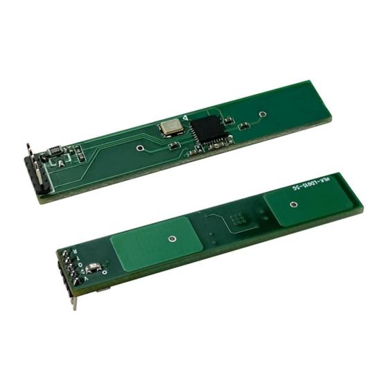
HLK-LD015-5G requires 3 pins by default, namely VCC, GND and OUT. At this time, the
induction delay and induction distance are fixed values. If you need to adjust the induction delay
and induction distance and other related parameters, you need to add 2 pins, RX and TX, on the
hardware as shown in Figure 3. In software configuration, RX and TX can be used as I/O ports or
UART ports to adjust module parameters. These two PINs are regarded as I/O ports by default,
where TX is used to adjust the sensing distance, its sensing distance is 4~6 meters at low level
while 3~5 meters at high level; RX is used to adjust the delay time, its sensing delay time is 30S at
low level while 2s at high level. When the sensing is triggered again within the delay time, the
timing will restart. RX and TX can also be used both as UART port to adjust the module parameters,
and serial ports.
HLK-LD015-5G
Minimum
Typical
Value
Value
5725
0.5
4.5
38
30
10
-30
Maximum
Value
5875
1
5
5.5
5
0
50
3
5
4
6
85
Page 3 / 6
User Manual
Unit
Remarks
MHz
mW
LDO is not attached by
V
default
V
V
mA
Adjustable according
M
to specific needs
Related to sensitivity
M
and hanging height
Adjustable according
S
to specific needs
Adjustable according
Lux
to specific needs
°C