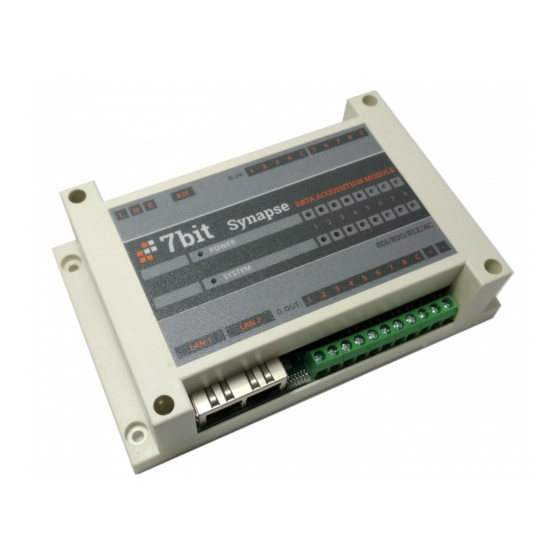
7bit Synapse Manuel d'instruction
Parcourez en ligne ou téléchargez le pdf Manuel d'instruction pour {nom_de_la_catégorie} 7bit Synapse. 7bit Synapse 2 pages. Mqtt/modbus tcp/8di/8do(r)/32x1-wire/ac industrial digital input/output module for remote process control and data acquisition

MQTT/Modbus TCP/8DI/8DO(R)/32x1-Wire/AC
Industrial digital input/output module for
remote process control and data acquisition
Thank you for choosing our product. The 7bit Synapse module designed as a remot e
Ethernet DIO, counter and 1-Wire temperature
automation and monitoring applications. MQTT connectivity option allows you to
create cloud-based monitoring & control applications. Built-in AC power supply and
2-port Ethernet switch simplify installation and cabling, extending network length and
allowing to install the module into existing network w/o extra equipment. The setup
is made easy with the web-config page.
Module Synapse is an OPEN-TYPE device. It should be installed in a control
cabinet free of airborne dust, humidity, electric shock and vibration
The device is operating at dangerous voltage rating. High voltage also may
occur at output terminals during it work. Please do not touch these
terminals when the device is powered on. DO NOT connect AC power to any
of input terminals, otherwise serious damage may occur. Please double
check all wiring before Synapse is getting powered up
The following abbreviations are used for Modbus registers functions: C -
Coils, DI - Digital Inputs, HR/IR – Holding/Input Registers, and their data
format: W - Word (2 bytes), DW - Double Word, b – bit. R/W – Read/Wri t e
mode.
1. Technical specifications
Power supply
100 - 220 VAC, 50/60 Hz, Max power consumption: 3W
Communication
2 x Fast Ethernet switch, Modbus TCP, MQTT
INPUTS
8 x DI with single common,
Points
Isolation voltage 5000 Vac / 500 Vdc, 12 - 24 AWG
Type
24 VDC (SINK / SOURCE) or internal isolated DC supply
Counters & Time on
8 + 8 / 8 + 8 (for each DI & DO channel), 32-bit capacity,
totalizers
static memory, 1 kHz max. sw. frequency
Jitter filter
Individual for each channel, adj. 0 ~ 20ms (default 20ms)
OUTPUTS
8xDO, 12 - 24 AWG, two groups DO 1 - 4 and DO 5 - 8
Points
(SSR or Relay or SSR + Relay)
220 VAC / 30 VDC, 2A.
Relay
Max. frequency: 1 Hz, ~10 ms response time
Synapse
SSRs*
Points
Bus length
Operation -
Storage / Protection
Weight
input module for industrial
* made by order
2. Dimensional drawing
3. Wiring
3.1 Ethernet. Synapse has an embedded switch which make easy to connect numerous
modules simply, connecting them to each other in "daisy chain". As it is true Ethernet
witch, each connection may be up to 100 m. It is also possible to connect the devic e
at any breaking of existing Ethernet link.
AC, 85 - 220V 2A, Zero-crossing switching.
Max. frequency: 100 Hz
1WIRE
Up to 32 digital thermometers DS18B20
Up to 200 m.
ENVIRONMENTAL
0°C - 55°C, 5 - 90% (w/o condensation), -25°C - 70°C, 5 - 95%
IP40
200 g.
3.2 Digital inputs
Address
Description
DI0 ~ DI7
Digital Inputs
HR20 ~ HR27
Input filters (0 - disabled)
Use internal power supply for powering inputs via long cables with caution
due to low voltage and voltage drop you may have unstable DI signaling
3.3 Digital outputs There are 2 groups by 4 outputs, each can be either relay or SSR
(by order) type. Due to Zero-cross detection unit, SSR provides comfort switching for
any AC load in the range 85 - 220V, 2A. Relay outputs is commonly used for dry
contacts and DC signals commutation.
Address
Description
C0 ~ C7
Digital outputs
To avoid sparks, limit switching currents and increase switching lifetime for
the outputs, it is strongly recommended to use extra snubber circuits for
inductive loads.
3.4 Safe power on After power on the module can restore its outputs to a previous
state. For many applications it is convenient feature, but for some not. E.g. some parts
of a heavy machine may accidentally move on repower and cause dangerous situation.
To avoid this problem now there is a special setting to choose output state after
repower:
Address
Description
HR35
Safety state 0 – off, 1 - on
3.5 PWM for triac outputs The duty cycle is set as 0 .. 100 which means how many
periods of AC current from one hundred will power the load. So the time base of the
PWM is 100 * 20 ms (1/50Hz) = 2 seconds. Before using DO for common ON – OFF
control set PWM values to 0.
Internal
supply
Data
R/W
Default
b
R
-
W
R/W
20
Data
R/W
Default
b
R/W
-
Data
R/W
Default
W
R/W
0 (off)
