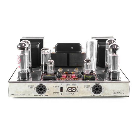
DYNACO Stereo 70 Manuel de restauration - Page 12
Parcourez en ligne ou téléchargez le pdf Manuel de restauration pour {nom_de_la_catégorie} DYNACO Stereo 70. DYNACO Stereo 70 20 pages. Series ii tube amplifier
Également pour DYNACO Stereo 70 : Manuel de restauration (5 pages), Manuel du propriétaire (12 pages), Instructions pour l'assemblage (16 pages)

Page 12
38. Trim to length and connect the four Left output transformer leads (Yellow,
Orange, Brown, Black) to the Left speaker output terminals as shown in figure 1.
39. Prepare a 15" black / green twisted pair of 22 ga.Teflon insulated wire. From one
end connect the black lead to the speaker output terminal that is connected to the
left output transformer Black lead. At the same end connect the green lead to the
speaker terminal connected to the left output transformer Yellow lead. Route the
twisted pair along the left edge of the amplifier and then along the front of the
amplifier so that it arrives near the input terminals.
40. Trim to length and connect the four Right output transformer leads (Yellow,
Orange, Brown, Black) to the speaker output terminals as shown in figure 1.
41. Prepare a 15" black / red twisted pair of 22 ga.Teflon insulated wire. From one
end connect the black lead to the speaker output terminal that is connected to the
Right output transformer Black lead. At the same end connect the red lead to the
speaker terminal connected to the right output transformer Yellow lead. Route the
twisted pair along the right edge of the amplifier and then along the front of the
amplifier so that it arrives near the input terminals.
42. Connect the shorter of the two power transformer black leads to the center lug of
the fuse holder as shown in Figure 1.
43. Connect the remaining (longer) black lead of the power transformer black leads to
terminal 1 of the power switch as shown in Figure 1.
44. Locate the two the Power transformer (not output transformer) Red leads and
lightly twist them together orienting them toward the left past the underside of V1
(rectifier tube socket). Trim to length and connect one to V1/pin 4. Connect the
remaining red wire to V1/pin6.
45. Locate the two the power transformer White (due to age these may also appear as
Yellow) leads and lightly twist them together orienting them towards the V1
(rectifier tube socket). Trim to length and connect one to V1/pin 2. Connect the
remaining red wire to V1/pin8.
46. Locate the power transformer Green/Yellow lead and the power transformer
Brown/Yellow lead. Twist (if possible). Trim to length and attach one lead to the
first lug (nearest the front of the amplifier) of the 4 pin terminal strip (this lug also
connects to one of the outer leads of the ceramic cap). Trim to length and connect
the remaining lead to the third lug of the 4 pin terminal strip (this lug also
connects to the remaining outer leg of the ceramic capacitor).
47. Locate the power transformer Red/Black lead and connect this to lug #4 (the
remaining free lug, nearest the power transformer) of the 4 pin terminal strip
mounted between the bias potentiometers.
48. Locate the power transformer Red/Yellow lead and securely connect it to the
ground lug (center lug) of the 3 lug terminal strip located to the right of the right
bias potentiometer (near the original Quad electrolytic capacitor). Make Note -
This is system ground.
49. Locate the Red leads for each of the output transformers and route each to appear
near the 3 lug terminal strip. Trim to length and attach to lug #3 (nearest the
Dynaco Stereo 70 Power Amplifier
Restoration Manual
Detailed Procedure & Guide
R0 4-03
12
