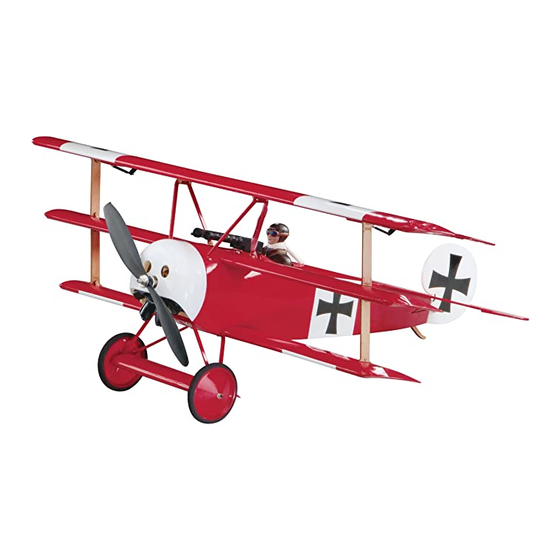
GREAT PLANES fokker DR-1 Manuel d'instruction - Page 8
Parcourez en ligne ou téléchargez le pdf Manuel d'instruction pour {nom_de_la_catégorie} GREAT PLANES fokker DR-1. GREAT PLANES fokker DR-1 20 pages.

❏
6. Use a fi ne-point felt-tip pen to mark the outline of the
fuse onto the bottom of the stab.
❏
7. Remove the stab from the fuse. Use a sharp #11 hobby
knife or the "Expert Tip" that follows to cut the covering from
the stab just inside the lines you marked. Use care to cut
only the covering and not the wood. Cutting the wood will
weaken the stab and it may break in fl ight.
HOW TO CUT COVERING FROM BALSA
Use a 25-watt soldering iron to cut the covering from the
stab. The tip of the soldering iron doesn't have to be sharp,
but a fi ne-tip does work best. Allow the iron to heat fully.
Use a metal straightedge to guide the soldering iron at a
rate that will just melt the covering and not burn into the
wood. The hotter the soldering iron, the faster it must travel
to melt a fi ne cut. Allow the heat to melt the covering. Do
not apply much pressure or the wood may be damaged.
Peel off the covering.
❏
8. Reinstall the stab onto the fuse. Use the string method to
align the stab and glue it in place with thin CA.
❏
9. Temporarily attach the elevator to the stab with four CA
hinges. IMPORTANT: There is a left and right side to the
elevator. The bottom, right side of the elevator has a small
slot for the elevator control horn. Be sure the elevator half
with the slot is on the bottom, right side of the fuse. Use
T-pins to hold the CA hinges centered in the elevator as you
did when installing the ailerons on the Top wing. Apply 3
drops of thin CA on the top and bottom of each hinge.
❏
10. Install the 10mm x 21mm [3/8" x 13/16"] CA hinge
in the rudder and test fi t it into the rear of the fuse. Adjust
the rudder so that the bottom is even with the bottom of the
fuse. Use a small modeling square to make sure that it is
perpendicular to the stab. Apply 3 drops of thin CA on each
side of the hinge.
❏
11. Test fi t the tail skid at the rear of the fuse. When
satisfi ed with the fi t, attach the tail skid to the bottom of the
fuse using medium CA.
RADIO INSTALLATION
Install the Motor & ESC
Note: You will need to have your motor battery charged later in
this section. We recommend that you start charging it now so
you do not have to wait for it to charge later. Make sure to closely
follow the charging instructions for charging LiPo batteries. We
also recommend that you remove the bottom wing for this
procedure for better access to the inside of the fuse.
❏
1. Use epoxy to join the two piece motor mount. Make
sure all openings align.
8
