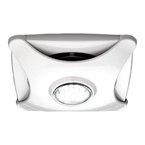
HiB 31900 Instructions de fixation - Page 2
Parcourez en ligne ou téléchargez le pdf Instructions de fixation pour {nom_de_la_catégorie} HiB 31900. HiB 31900 2 pages. Ceiling mounted ventilation illuminated fan

Position the Fan on the Ceiling
1) Choose a suitable position for your fan
according to Figure 1 opposite. Use a
cable fi nder to check if there are any
buried cables or pipes in the ceiling.
Ceiling mounted ventilation should
be ducted through the roof space, by
ducting to an external soffi t under the
eaves or grille in the slope of your roof.
NB: Ducting installed between a fl oor
and ceiling can only run between joists,
not across them.
2) Mark the position of the vent fascia with
a pencil in a suitable position on the
ceiling, making sure that it is between
the joists.
3) Drill a 9mm hole through the ceiling
anywhere along the edge of the pencil
line. Now cut out the hole with a pad
saw.
4) Hold the vent fascia against the ceiling
and mark the position of the fi xing
holes. Fix the unit in place using suitable
heavy duty plasterboard fi xings (not
supplied).
5) Attach fl exible ducting (not supplied)
with the metal hose clamps. Ensure that
the ducting has a smooth fl ow towards
the external grille to minimise air
resistance. Follow a similar procedure
for the outside wall grille.
Electrical Connection
1 casing
2 terminal block
3 lamp terminal block
4 lamp socket
5 hole for power wires
6 holes for fan mounting
1) Ensure the domestic electrical mains
supply to which the fan is being
connected is turned off. This product
is designed to be connected to an on/
off switch outside the bathroom, or to a
ceiling mounted pull cord switch.
2) Remove the protecting grille and lamp.
This product is SELV and the mains
power should be connected to the
transformer supplied. See diagram
below.
3) Connect the electrical wiring to the motor according to the diagram below.
- Switching fan and luminaire on/off together with one switch:
4) Fix the fan to the ceiling using 4 screws.
5) Replace the cover and protective grille.
Figure 1
60cm
zone
2
zone
zone
2
1
All installations must comply with guidelines which are based on a zonal concept. The diagram above illustrates this concept
and must be followed to ensure the safe installation of bathroom ventilation. These regulations apply to domestic installations
only. Installations must be made in accordance with the current IEE wiring regulations and relevant building regulations. HiB
recommends that all electrical bathroom products should only be fi tted by a suitably qualifi ed, Part P registered electrician.
This product is IPX4 Rated, and suitable for installation in Zone 2 and Outside Zones.
60cm
60cm
60cm
zone
2
outside
zone
zone
zone
2
2
60cm
zone
radius
2
zone
1
