DAYTEK MK2 MINI Manuel du produit - Page 4
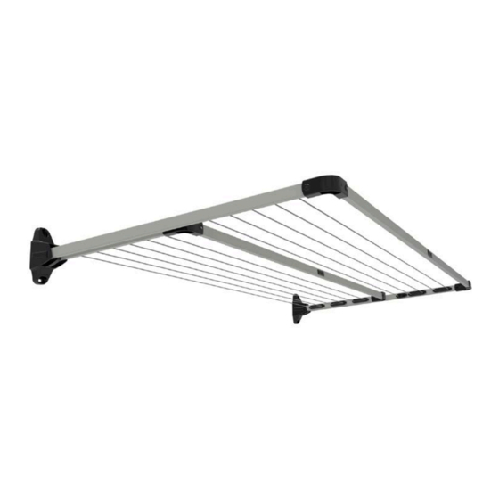
Parcourez en ligne ou téléchargez le pdf Manuel du produit pour {nom_de_la_catégorie} DAYTEK MK2 MINI. DAYTEK MK2 MINI 8 pages. Fold down clotheslines

INSTALLATION PROCEDURE
1. MOUNT SIDE ARMS TO WALL
Note: For ground mount kits installation skip
to step 1.4
1.1 Mark wall bracket positions and centres. Refer
to Figure 1 for fixing centres measurements for
the model you are installing. The vertical distance
between wall bracket mounting holes is 170mm.
Take note of the recommended installation height.
1.2 Use 8mm x 50mm masonry anchors or suitable
wood screws to fasten to your selected surface.
Consult a hardware store or builder if unsure.
1.3 Drill holes suitable to your chosen fixings
squarely into your wall at the marked location.
1.4 Fix the pre-assembled Side Arms to the wall.
Note the Left and Right hand assemblies (Daytek
logo should always be upright – refer to Fig. 1A)
2. CONNECT CORNER BRACKETS
AND FRONT BAR
2.1 Attach a Corner Bracket over
each end of the Front Bar and
secure with the supplied nuts &
bolts (See Fig. 2A – 2C). For Twin
model, assemble and attach the
Inner Front Bar first (shorter one).
2.2 Lock each side arm into the
upright position. To do this lift
each side arm upwards to the
maximum point of travel and push
inwards until it hits a hard stop, then
release (refer to operating diagrams
on page 7).
2.3 Install Front Bar to the Side Arms
and secure with supplied nuts &
bolts (See Fig. 2D – 2F).
4
1A
2A
2C
2E
TO DETERMINE LEFT
AND RIGHT
PRE-ASSEMBLED
SIDE ARMS ALWAYS
ENSURE DAYTEK
LOGO ON BRACKET
IS UPRIGHT AND
LINE BRACKETS ARE
FACING INWARDS
2B
2D
2F
