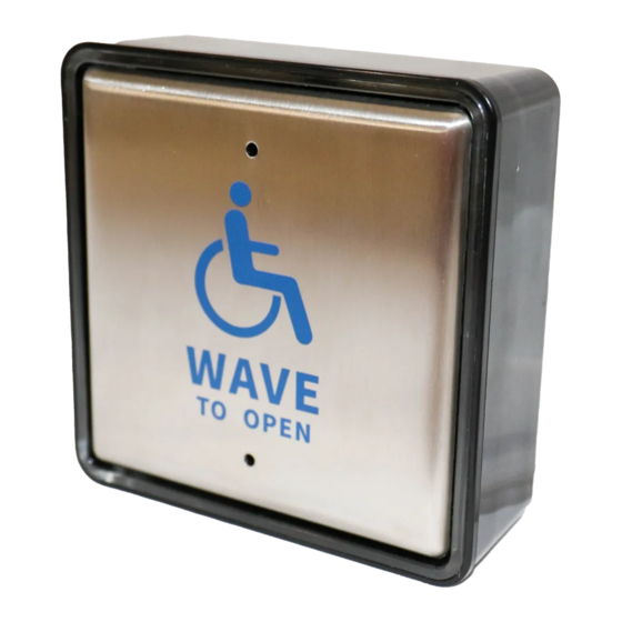
Automatic Door Accessories ADA 215S Instructions d'utilisation - Page 2
Parcourez en ligne ou téléchargez le pdf Instructions d'utilisation pour {nom_de_la_catégorie} Automatic Door Accessories ADA 215S. Automatic Door Accessories ADA 215S 2 pages. Wireless touchless switch kit

USA FCC
Part 15
Indoors
International
level
1
Safety Instructions
Thank you for your purchase. For proper use and operation,
!
please read this manual carefully before installation.
2
Overall Product Characteristics
Large Stainless Steel panel design.
The embedded capacitive sensor chip turns the metal surface panel into the sensors
antenna. The Switch functions when detecting the charge from a hand entering the
induction activation zone.
This replace's the traditional mechanical contact switch, with a non-contact wave switch,
leaving a clean and hygienic surface.
Advanced software algorithm, allows for strong anti-interference.
The induction distance is adjustable from 1" - 3"
2.4 G Hz wireless communication technology, creates excellent frequency
consistency and high wireless transceiver stability.
Low power consumption sensor panel design allows for long battery life.
Receiver's large capacity output can be used with automatic doors, and
access control systems.
Switch is equipped with a blue LED indicator. Upon receiving the signal, the receiver
holds the relay output for 1.5 seconds.
Receiver has a wide voltage input design accepting 12 ~ 30V DC power input.
3
Product Overview
①
3
2
3
8
6
7
1 LED indication (red light flashes in the power-on learning state,
the red light is off when the learning is completed, and the action
blue light is on)
2 Sensing surface
3 Front panel assembly screw hole
4 Induction distance Potentiometer
5 Connection terminal
6 ABS box mounting location
7 Face cover mounting posts
8 Battery compartment
Operation Instructions
ADA215S Wireless Touch-less Switch
4
5
Utilizes a self-learning code. The transmitter must be paired with the
receiver.
Pairing method: press the learn button on the receiver for 1 second to make
the indicator light turn blue and enter the learning state then activate the
transmitter, the blue LED flashes, indicating a successful pairing.
Deletion method: Press and hold the learning button for 5 seconds, the blue
light flashes quickly deleting all codes previously paired with this receiver.
4
Induction distance adjustment
Turning clockwise increases sensing distance to a
maximum of 3". While turning counterclockwise
1 in
3 in
decreases sensing distance to a minimum of 1".
5
I/O wiring definition
NO
NO
orange
NC
NC
yellow
COM
COM
blue
green
AC/DC 12∽30V
power input
red
6
Typical wiring diagram
NO
orange
NC
yellow
COM
blue
green
Automatic door controller power
supply (open door contact)
red
AC/DC 12~30V
Receiver and automatic door controller wiring diagram
Output status selection
7
M
With the switch in the M position, the output is Momentary. Each time the
1
transmitter is pressed, the receiver will change state and Momentarily hold
L
for 1.5 seconds. Most applications will use this option.
With the switch in the L position, the output is Latching. When the wireless
M
transmitter is activated, the output state will change and hold (latch) in that
changed state. A second activation of the wireless transmitter will change the
L
state of the output back to it's original state and it will hold (latch) in that state.
Technical Specifications
8
Receiver
AC / DC12~30V
Power supply:
30mA
Static current
Action current
74mA(DC12Vpower supply)
1A
Main contact capacity
Wireless switch
Power supply
6V(4 pcs 1.5V AA batteries)
≤5 0 uA
Static current
500 Times / day, for 330 days
Battery life
Emission current
12mA
More than 100 feet clear line of sight
Launch distance
-43*F - +113*F
Working temperature
Working humidity
10∽ 9 0 %RH
Size
5 in(L)× 5 in(W)× 1.75 in(H) (panel)
4.75 in(L)× 2 in(W)× 1.25 in(H)(Receiver)
24VDC
