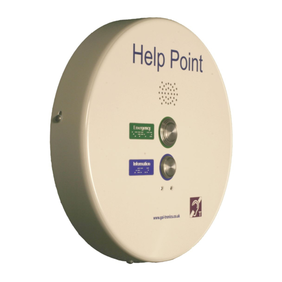
GAI-Tronics PHP400 Manuel d'installation et d'utilisation - Page 7
Parcourez en ligne ou téléchargez le pdf Manuel d'installation et d'utilisation pour {nom_de_la_catégorie} GAI-Tronics PHP400. GAI-Tronics PHP400 20 pages. Analogue version (1090/1099 series) with ampetronic hls-dm2 induction loop amplifier 230v ac power supply
Également pour GAI-Tronics PHP400 : Manuel d'installation et d'utilisation (20 pages), Manuel de conception, d'installation et d'utilisation (20 pages)

1. Induction loop audio (2 conductors)
2. DC power (2 conductors)
3. Earth cable
4. Telephone cable (if already through one of the cable entries in the rear section).
These cables are deliberately short, but will allow the front section to sit to the left of the rear
for set-up purposes if required.
Installation method
5.5.
The Help Point is intended for vertical installation to a solid wall or suitable post as detailed
below.
1. Choose a suitable location for the Help Point, bearing in mind the weight of the unit,
and that the operating button(s) should normally be in the range 1200 – 1400mm
from the ground for ease of access by people in wheelchairs.
2. Mark the wall or surface with fixing centres as shown above. If necessary use the
rear section to help mark the centres. Do not use the rear section as a drilling
template.
3. Select fixing screws or bolts appropriate to the type of wall or surface, suitable to
support the unit. Drill fixing holes to suit.
4. Separate the front and rear sections of the Help Point, taking care to disconnect
interconnecting cables as described in section 5.4.
5. Secure the rear section to the wall, making sure that the fixing holes are sealed to
prevent water ingress using nylon washers or other appropriate sealing methods.
6. Bring power and telephone cables into the unit through one or both of the cable entry
holes. Cables will normally be contained in conduit, but glands may also be used.
7. The power cable is terminated directly to the terminal block provided, and secured
using the cable restraint.
8. The telephone cable should be left long enough to allow connection to the front
section (approximately 450mm from entry point) where it is terminated into screw
terminals.
9. Ensure that cable entries are sealed to prevent water ingress. If only one cable entry
is used, the blanking plug fitted to the other positions must be left in place.
10. Connect induction loop audio, dc power, telephone and earth cables to the front
section of the case as shown below.
11. Apply power. The LED on the internal PSU should illuminate. Test the unit by
pressing a front panel button. You should hear dial tone even if no autodial number
has been programmed.
12. Fit the front section over the rear section and secure in place using the 4 security
screws. Ensure no cables are trapped between the 2 sections.
PHP400 Analogue Help Point.
7
