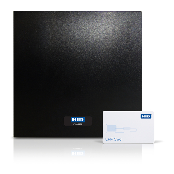
HID iCLASS SE U90 Series Manuel d'installation - Page 7
Parcourez en ligne ou téléchargez le pdf Manuel d'installation pour {nom_de_la_catégorie} HID iCLASS SE U90 Series. HID iCLASS SE U90 Series 9 pages.

I N STALLATI ON GUI DE
Instruções portugueses. Consulte as etapas em Inglês para gráficos em tamanho.
Lista de peças
1 - Leitor iCLASS SE
1 - Manual de instalação
2 - Parafusos Phillips a máquina nº 6-32 x 0,375 pol
2 - Parafuso de segurança chave nº 6 x 0,375 pol
2 - Conector de terminal de 7 pinos
1 - Conector de terminal de 10 pinos
1 - Vedação de montagem
1 - Caixa traseira
Especificações
NÚMERO
PRODUTO
DAS PEÇAS
ENTRADA (VCC)
BÁSICAS
U90
RDRSEU90
Relés
Três (3) relés sem alimentação para operação dos indicadores sonoros e visuais externos. Não devem ser utilizados
para Controle de Acesso. Tensão nominal de 30V CC, 2A resistivos.
Instalação
1
Montagem
Há diversas opções para serem utilizadas como superfícies de montagem (suporte para montagem em poste, concreto, metal,
parede, etc.). Refira-se ao Guia do Usuário do leitor ICLASS SE SE U90 para informações detalhadas.
200
VESA
CONDUIT
US
JBOX
100
75
75
EU
JBOX
EU
EU
JBOX
JBOX
EU
JBOX
75
75
US
JBOX
100
200
Orifícios de montagem devem ser
perfurados para combinação com o
suporte selecionado para o local.
This Installation Guide is for informational purposes only. HID makes no warranties, expressed or implied, in this summary. Company, product names and data used in sample output
are fictitious. Specifications are subject to change without notice.
© 2014 HID Global Corporation/ASSA ABLOY AB. All rights reserved. HID, the HID logo, and iCLASS SE are trademarks or registered trademarks of HID Global in the U.S. and/or
other countries. All other trademarks, service marks, and product or service names are trademarks or registered trademarks of their respective owners.
h id g l o b a l.co m
CORRENTE
VOLTAGEM DE
Standby
Max
AVG1
AVG2
12 VDC
320mA 400mA 1.0 A
24 VDC
160mA 200mA 0.5 A
Standby AVG - RMS current draw without a card in the RF field.
1
Maximum AVG - RMS current draw during continuous card reads. Not evaluated by UL.
2
Peak - highest instantaneous current draw during RF communication.
3
200
100
100
200
Modifique a junta para combinação com
orifícios grandes na placa de montagem e com
a área entre o suporte e a caixa, para criar uma
vedação contra elementos externos (refira-se
aos itens abaixo).
iCLASS SE
Recomendado
• Cabo, condutor 5-9 (Wiegand or Clock-&-Data)
• Alimentação DC linear
• Caixa de junção de metal ou plástico
• Ferramenta de segurança (para o parafuso antiviolação)
HID 04-0001-03
• Perfure com várias brocas para montagem do hardware
• Montagem do hardware
TEMPERATURA DE
OPERAÇÃO
PEAK3
-30° to 150° F
(-35° to 65° C)
An ASSA ABLOY Group brand
U90 (U90.915 & U90.865)
COMPRIMENTO DO CABO
Power Supply Lines
40 ft (12 m)
- 22 AWG
100 ft (30 m) - 18 AWG
Communication Lines
Wiegand / Clock-and-Data
500 ft (152 m) - 22 AWG
RS-485
4,000 ft (1,219 m) - 24 AWG
UL Reference Number Deciphering
x
Reader Colors:
K = Black
1
x
Wiring:
T = Terminal
2
x
Radio band
8 = 865 to 867 MHz
3
9 = 902 to 928 MHz
Apare a junta para combinar com a área de
contato
Acople a caixa com a junta instalada ao
suporte de montagem
NÚMERO DE
REFERÊNCIA UL
U90Ax
x
x
1
2
3
