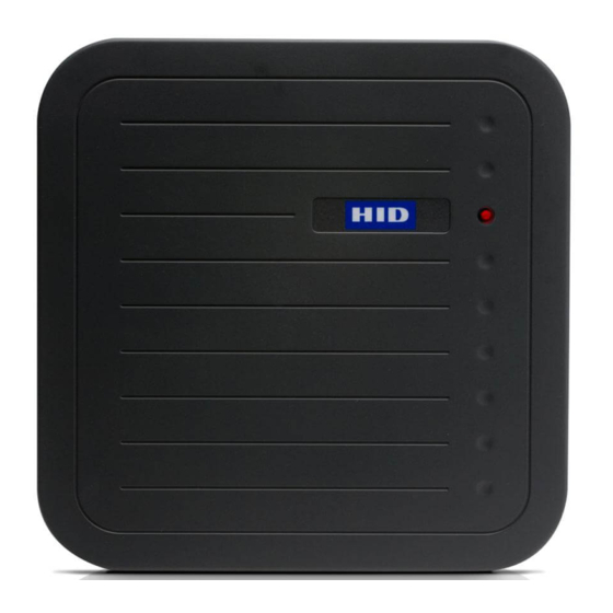
HID MaxiProx DFM Reader - 5375 Manuel d'installation - Page 13
Parcourez en ligne ou téléchargez le pdf Manuel d'installation pour {nom_de_la_catégorie} HID MaxiProx DFM Reader - 5375. HID MaxiProx DFM Reader - 5375 19 pages.

®
MaxiProx
Installation Guide
3
Installation Guidelines
3.1
Power Supply
The recommended power supply is 12 or 24VDC, nominal, 2.0A current rating, linear or switching
regulated. The MaxiProx cycles through varying power stages and has a peak current demand of
approximately 1.2A when in long range read mode. Average current consumption is about 260mA.
Failure to provide an adequate current capacity power supply will result in reduced read range.
CAUTION: The P2 shunt jumper is factory installed in the 24VDC position. Failure to install the
P2 shunt jumper in the correct position will permanently damage the MaxiProx unit. The
following states the P2 shunt jumper installation.
Power Supply Voltage
+24 VDC (21-28.5VDC)
+12 VDC (11.6-20.9VDC)
The use of a Power Switching Supply is not recommended for two reasons:
1. This type of supply does not provide adequate response to rapid transient current loads and also
generates radio frequency (RF) interference in the same band that the reader receives data and;
2. The power supply may generate noise that is large enough to be transmitted or conducted to the
MaxiProx that interferes with the reception of a card signal. Some switching power supplies are
not able to provide adequate regulation to the MaxiProx reader.
3.2
Installation near metal
Read range will be reduced if located on metal surfaces or in the vicinity of metal objects. The amount
of reduction will be a factor of the amount of metal and the distance the reader is from the metal. Metal
near the reader absorbs energy from the reader excite field and affects the signal being received from
the card by re-directing excite field transmissions into the receiver circuitry. Moving the reader away
from the metal objects reduces energy loss.
Try to limit the amount of metallic materials installed near the MaxiProx. Use a plastic electrical box if
possible. Avoid installing conduit and other metal hardware within 2-inches of the back of the reader or
closer than 4-inches from large metal surfaces. The typical read distance specification (24-29 inches at
21-28.5 VDC or 21-26 inches at 12 VDC) refers to operation without metal in the vicinity of the reader.
The read distance will be reduced if metal is installed nearby.
The MaxiProx generates a magnetic field on all sides of the reader. Any metal that conducts electricity,
especially metal that contains iron, steel or copper will interfere with the field and reduce the effective
read range (this will happen even if the metal is behind the reader). It helps to put a non-metallic spacer
between the reader and the metal object.
3.3
Radio Frequency Interference
Motors and electronic devices generate RF noise that may interfere with the reception of the signal
from a transponder. The affect of RF noise is typically a reduction of read range. The MaxiProx is
susceptible to RF interference, as are all devices that receive RF signals. The read range is affected by
the amount of interference (noise) in the area. Common sources of RF interference are power supplies,
electrical and electronic equipment, some types of lighting, computers and monitors, motors and
generators. Moving the reader to a location known to be free of interference and testing read range
there will help to isolate RF interference as a factor in low read range situations.
The MaxiProx should not be mounted within six feet of any monitors (VDTs or CRTs) because the scan
frequencies of most monitors include frequencies that may interfere with the signal received from the
access control cards.
March 2012
Jumper Position
P2 across pin 2 and 3
P2 across pin 1 and 2
© 2008-2012 HID Global Corporation. All rights reserved.
Part No. 5375-901, Rev E.1
Page 13 of 19
