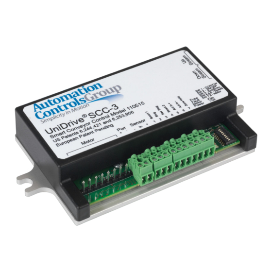
Automation Controls Group 110515 Manuel d'installation et de dépannage - Page 9
Parcourez en ligne ou téléchargez le pdf Manuel d'installation et de dépannage pour {nom_de_la_catégorie} Automation Controls Group 110515. Automation Controls Group 110515 11 pages. Smart conveyor control generation iii

Braking & Zero Motion Hold (ZMH)
3.8.4
When DIP Switch 8 is placed in the OFF position, motor
dynamic braking will be used to bring the motor to a stop as
quickly as possible. When DIP switch 8 is in the OFF position,
Zero Motion Hold (ZMH) will also be active so that if the
motor shaft continues rotating due to inertia, increasing
current will be applied to the three motor phase windings in
an attempt to hold the motor shaft at the requested stop
position.
When DIP Switch 8 is placed in the ON position, the motor
will be allowed to coast and no motor braking will be
applied.
Slug & Reverse Slug Input Operation
3.8.5
1.
Use Slug (a PNP input) to override all logic internal to the
control and force this zone and all upstream zones to run
regardless of whether they are occupied or empty. Slug is
sometimes also referred to as Jog
NOTE: When this signal is active, parcels will be
pushed off the end of the conveyor if there is
nothing in place to receive them.
2.
Use Rev Slug (a PNP input) in one of two ways:
Alone: Assert it by itself to cause the zone and all
upstream zones to coast. The motors will not be
energized and will not provide any active braking power.
In Combination: Assert it in combination with the slug
input to override all logic internal to the control and force
this zone and all upstream zones to run in the reverse
direction regardless of whether they are occupied or
empty.
NOTE: When this signal is active, parcels are pushed
out of the upstream end of the zone regardless of
the availability of any upstream device to accept the
parcel. In this scenario, if there is nothing there, any
parcels could potentially fall to the floor.
______________________________________________________
Other Modes of Operation
3.8.6
If you need to do something other than those things listed
above, please contact either our Sales or Application
Engineering Departments for assistance at (619) 677-6530.
4
Special Functions
Zone Hold Input
4.1
When the zone hold input (I/O pin 7) goes active, prior to an
object reaching the primary (downstream-edge) sensor, then
that object will be held in that zone and will not exit while the
zone hold signal remains active.
All objects in the upstream zones will also be held while the
zone hold input is active.
When an object is actively exiting the zone hold input will have
no effect on that object exiting.
Configuring an SCC-3 as a BMC
4.2
In certain applications it may be necessary to eliminate the 2.5
second motor run-on feature which is a part of the Search &
Rescue function (see section 4.3). To accomplish this, the SCC-3
control can be configured as a Basic Motor Control (BMC) or
standalone motor control. To accomplish this implement the
following steps;
1)
Place Control DIP switch 3 in the ON position (slide the
switch to the right)
2)
On the GREEN 3-pin sensor connector, wire the sensor
input (center pin) to the sensor +voltage (pin on the right).
3)
Apply a 24Vdc signal to the Slug input (I/O pin 2) to start
and stop the motor
4)
When the Slug input goes high then I/O pin 4 will go high
to indicate that the motor is running
Search and Rescue
4.3
This function has been added to the control in order to avoid
situations where parcels could become stranded between
photo sensors, creating a nuisance at the very least. The
function works under the following circumstances:
During Power Up
After Discharge of a Parcel from the Downstream Edge of a Zone
After Removal of a Slug Signal (if Rev Slug is Not Active)
After Removal of a Rev Slug Signal (if Slug is Not Active)
During Power Up
4.3.1
When the power is off, parcels are not tracked. When power is
first applied, each control goes through a self-check and report its
firmware revision as described in 5.2 Firmware Version Display.
Beginning at the Exit end and then flowing zone by zone after very
brief intervals to avoid creating high inrush current at the power
supply, each zone then runs for up to 2.5 seconds or until a parcel
arrives at the respective zone sensor, whichever comes first.
In this fashion, any parcels that may have been stranded between
sensors when power was removed are discovered and will then
be processed by the conveyor in either ZPA or ZIP control mode as
determined by the switch settings.
NOTE: 2.5 seconds is a nominal time period. The actual
time is adjusted up if zones are set to a lower than
maximum speed. For example, if a zone is set to half its
maximum speed, the run time is doubled to 5.0 seconds.
After Discharge of a Parcel from the
4.3.2
Downstream Edge of a Zone
It is not unusual for operators who are manually loading parcels
onto a conveyor to place two small parcels in a single zone. If the
zone stopped immediately after a parcel passed its downstream
sensor the second parcel could become stranded. Therefore each
zone will operate for up to 2.5 seconds after these events. When
the zone is already running, very little additional power is
consumed. This is a local function that directly affects only the
zone that just discharged its parcel.
SCC-3 Product 110515 Revision 1.3 April 19, 2018 | Page 9
