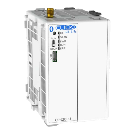
Automation Direct CLICK PLUS C2-02CPU Manuel de démarrage rapide - Page 3
Parcourez en ligne ou téléchargez le pdf Manuel de démarrage rapide pour {nom_de_la_catégorie} Automation Direct CLICK PLUS C2-02CPU. Automation Direct CLICK PLUS C2-02CPU 11 pages.

Hardware Installation, continued
CAUTION
Discharge static electricity before installation or
wiring in order to avoid electric equipment damage.
MOUNTING
The CLICK PLUS can be mounted on DIN rail or surface
mounted using built-in mounting tabs.
DIN Rail Mounting
Pull tab
down.
When installing on DIN
rails, always use end brackets
on both ends of assembly.
(AutomationDirect p/n DN-EB35)
Use 35mm width DIN Rails.
Use M4 size screws when you
surface mount.
Tighten the screws with a spring
washer and a small round washer
and torque 0.5 to 0.6 N·m.
ANTENNA MOUNTING
The CLICK PLUS CPU uses a single 2.4 GHz antenna for
both Bluetooth and wireless LAN connections. It can use an
SE-ANT210 direct-mount antenna, but for a continuous
WLAN connection from within a metal enclosure an
SE-ANT250 remote-mount antenna is recommended.
Copyright© 2020, Automationdirect.com Incorporated/All Rights Reserved Worldwide
C2-02CPU Quick Start Guide
Push tab
Click
up until...
Surface Mounting
Upper
Mounting Tab
Lower
Mounting Tab
SE-ANT250 Remote-mount antenna
WIRING
24VDC power is supplied to the CLICK PLUS CPU through
wiring connected from the power supply output to the 4-pin
connector located on the bottom of the CPU unit.
16–28 AWG wiring is supported. We recommend using
crimping ferrules on all wire terminations for a more secure
connection. The following crimping ferrules are recommend-
ed for the 24VDC power terminals.
Company
Type
Model No.
AutomationDirect Ferrule V30AE000009
V30AE000041
* Maximum tightening torque is 0.22 to 0.25 N·m.
Take care not to contact adjacent terminal.
Please use SELV (as defined by UL61010-2-201) and Limited
Energy (as defined by UL61010-1, 9.4) power supply.
CLICK power supply C0-00AC or C0-01AC is recommended.
CAUTION
Do not operate without first installing safety
cover over power supply leads .
CLICK PLUS CPU
CLICK Power Supply
24VDC
0V
G
24VDC power is supplied to the CPU unit through wiring connected from
the power supply output to the 4-pin 24VDC input connector located on the
bottom of the CPU unit.
CAUTION
DO NOT USE the PF connector. Leave this terminal
unconnected. Connecting the PF terminal to another
device may cause damage to the CLICK PLUS CPU.
Power supply symbols listed on the equipment are indicated
by the symbols shown below.
Name
Description
DC
Direct current
G
Functional earthing
Safety instruction for
CAUTION
battery replacement
I/O wiring is discussed in each module's documentation.
www.automationdirect.com/click-plc
3505 HUTCHINSON ROAD
CUMMING, GA 30040-5860
1-800-633-0405
Compliant Wire
0.2–0.5 mm
2
(22–26AWG)
OPTION SLOT MODULE (OPTIONAL)
STACKABLE MODULES
(OPTIONAL)
24VDC
0V
PF
G
Symbol
IEC6047 No. 5031
IEC6047 No. 5017
ISO 7000 No.0434B
3
