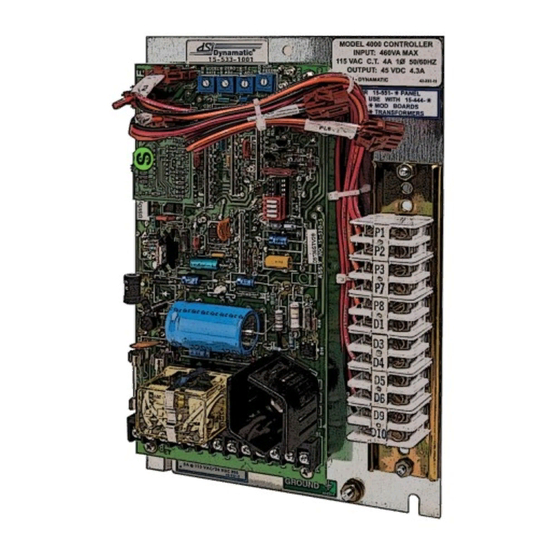
Dynamatic 4000 Fiche d'instruction - Page 2
Parcourez en ligne ou téléchargez le pdf Fiche d'instruction pour {nom_de_la_catégorie} Dynamatic 4000. Dynamatic 4000 13 pages. With dancer position
Également pour Dynamatic 4000 : Fiche d'instruction (15 pages), Fiche d'instruction (14 pages), Fiche d'instruction (13 pages), Fiche d'instruction (14 pages)

Introduction ............................................................................................................................................. 1
Connection Diagram for Standard Enclosure 4000 Controller ............................................................... 3
Schematic Diagram for 4000 controller .................................................................................................. 4
Connection Diagram for 4000 Panel Mount and 4050 Controllers ........................................................ 5
Schematic Diagram for 4050 controller .................................................................................................. 6
Tach Follower PCB 15-444-1 ................................................................................................................... 6
General Description ................................................................................................................................. 7
Visual Inspection ...................................................................................................................................... 7
Preliminary Adjustments .......................................................................................................................... 7
1.
Operator Controls................................................................................................................................ 7
2.
Main PCB 15-530-5 or 15-530-6 .......................................................................................................... 7
Trimpot Illustration ................................................................................................................................. 8
3.
Tach Follower Mod PCB 15-444-1 ....................................................................................................... 8
Adjustment Procedure ............................................................................................................................. 8
3.
Zero Adjust R19 with LED monitor ...................................................................................................... 9
Zero Adjust R19, Alternate Method- ...................................................................................................... 9
4.
Max Speed/Volts R21- ......................................................................................................................... 9
Max Speed/Volts R21 with LED monitor ................................................................................................ 9
Max Speed/Volts R21, Alternate Methods ........................................................................................... 10
6.
Time Constant (TC) Adjust R26 .......................................................................................................... 10
7.
Current Feedback R20*- .................................................................................................................... 10
8.
Accel Rate R18- .................................................................................................................................. 10
9.
Velocity Damping R22*- .................................................................................................................... 11
Renewal Parts List .................................................................................................................................. 12
2
