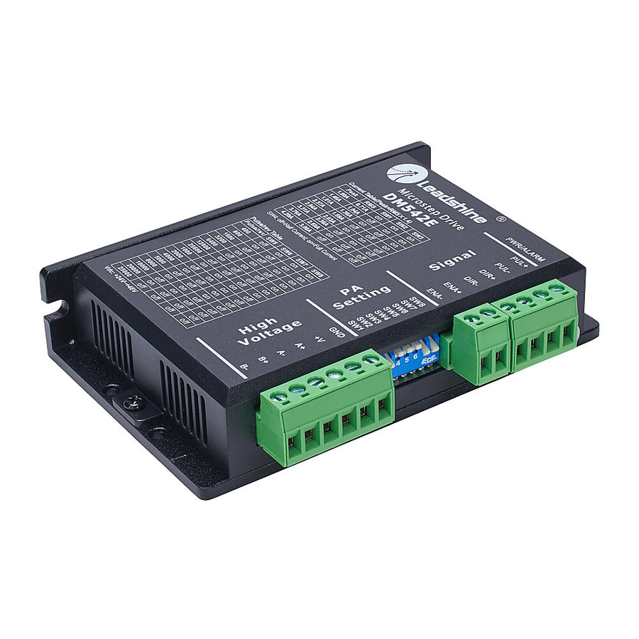
AutomationDirect Leadshine DM542E Manuel de démarrage rapide - Page 11
Parcourez en ligne ou téléchargez le pdf Manuel de démarrage rapide pour {nom_de_la_catégorie} AutomationDirect Leadshine DM542E. AutomationDirect Leadshine DM542E 17 pages. Stepper drives

DM805-AI
The DM805-AI drive is capable of pulse and direction as
well as analog input and speed control. Auto-motor config
on power up with self motor test capability. Comes with
built in potentiometers for adjusting speed limits and
accel and decel rates, and can be controlled via an external
potentiometer.
Specifications
Output Current
Supply Voltage
Pin Function
Connecting Devices to the DM805-AI Drive
4-lead motors are the easiest to connect, and the speed – torque of the motor depends on winding
inductance. To determine the output current of the drive, multiply the nameplate motor phase current
by 1.4 to determine the peak output current. If the motor runs too hot then multiply by 1.2 instead. For
6-lead and 8-lead motor wiring information, please refer to the drive User Manual.
The drives are designed to operate within a specific voltage input (see specifications table). When
selecting a power supply, choose a power supply with an output range within the minimum and
maximum of the drive and be sure to leave room for power supply fluctuation and motor back-EMF.
DM805-AI can be connected in a number of different ways depending on the desired mode of
operation. Wire the connections to the motor and power supply according to the applicable diagram
on the next few pages:
Leadshine Stepper Drives Quick Start Guide – First Edition – 11/04/2019
Electrical, Connector, and Environmental Specifications
Part Number
Run/Stop or Pulse
Direction or +Limit
Speed or (-)Limit
Enable/Disable
Leadshine Stepper Drives Quick Start Guide
DM805-AI
2�6–7�0 A peak
(0�3–5�0 RMS)
20–80 VDC
(60 VDC typical)
Pulse signal: 5V signal, single-ended input� High input is 4-5V,
Low input is 0-0.5 V. Minimum pulse width = 2.5 μs. Add a 1kꭥ
resistor for +12V signals, 2kꭥ for +24V signals.
Run/Stop Function: Close (pull low) to enable the motor�
DIR signal: 5V signal, single-ended input� High input is 4-5V, Low
input is 0-0.5 V. Minimum pulse width = 2.5 μs. Add a 1kꭥ resistor
for +12V signals, 2kꭥ for +24V signals.
Direction Function: requires 5μs setup time.
(+)Limit Function: Close (pull low) to stop motor movement in the
positive direction�
Speed: 5V signal, single-ended input� High input is 4-5V, Low
input is 0-0.5 V. Minimum pulse width = 2.5 μs. Add a 1kꭥ resistor
for +12V signals, 2kꭥ for +24V signals.
Speed Function (Low Speed/High Speed Mode): Close (pull low)
to select Lo Speed pot setpoint� Open (float high) to enable Hi
Speed pot setpoint�
(-)Limit Function: Close (pull low) to stop motor movement in the
negative direction�
Enable signal: 5V signal, single-ended input� High input is 4-5V,
Low input is 0-0.5 V. Minimum pulse width = 2.5 μs. Add a 1kꭥ
resistor for +12V signals, 2kꭥ for +24V signals.
Enable Function: Close (pull low) to disable the drive�
Page 11 of 17
