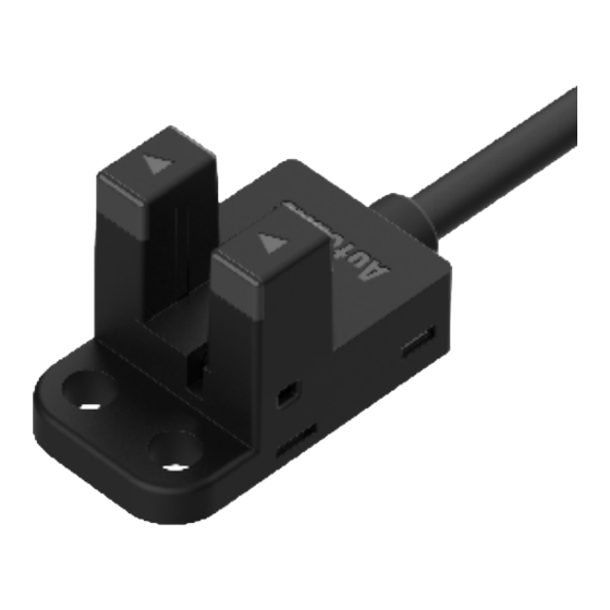
Autonics BS5 Series Manuel du produit - Page 3
Parcourez en ligne ou téléchargez le pdf Manuel du produit pour {nom_de_la_catégorie} Autonics BS5 Series. Autonics BS5 Series 4 pages. Groove-depth 9 mm photomicro sensors

Specifications
Series
BS5
Sensing type
Through-beam
Sensing distance
5 mm
Sensing target
Opaque materials
Min. sensing target
≥ 0.8 mm × 2 mm
Hysteresis
≤ 0.05 mm
Response time
Received light: ≤ 20 ㎲ , Interrupted light: ≤ 100 ㎲
Frequency response
2 kHz
01)
Infrared LED
Light source
Peak emission
940 nm
wavelength
Operation mode
Light ON-Dark ON selectable (control wire)
Indicator
Operation indicator (red)
Approval
Unit weight
Cable type: ≈ 50 g, Connector type: ≈ 30 g
01) Response frequency is the value getting from revolving the circle panel below.
1.8 mm
1.6 mm
Power supply
5-24 VDCᜡ ±10 % (ripple P-P: ≤ 10 %)
Current consumption
≤ 30 mA
Control output
NPN open collector / PNP open collector output model
Load voltage
≤ 30 VDCᜡ
Load current
≤ 100 mA
Residual voltage
NPN: ≤ 1.2 VDCᜡ, PNP: ≤ 1.2 VDCᜡ
Reverse power polarity protection circuit,
Protection circuit
output short overcurrent protection circuit
Insulation resistance
≥ 20 MΩ (250 VDCᜡ megger)
The square wave noise (pulse width: 1㎲) by the noise simulator
Noise immunity
± 240 VDCᜡ
Dielectric strength
1,000 VACᜠ 50/60 Hz for 1 minute
1.5 mm double amplitude (max. acceleration 196 m/s
Vibration
of 10 to 2,000 Hz in each X, Y, Z direction for 2 hours
Shock
15,000 m/s
(approx. 1,500 G) in each X, Y, Z direction for 3 times
2
Ambient illumination
Fluorescent lamp: ≤ 1,000
(receiver)
Ambient temperature
-20 to 55 ℃, storage: -25 to 85 ℃ (no freezing or condensation)
Ambient humidity
35 to 85%RH, storage: 35 to 85%RH (no freezing or condensation)
Protection rating
IP50 (IEC standard)
Connection method
Cable / Connector type model
Cable spec.
Ø 3 mm, 4-wire, 1 m
Wire spec.
AWG28 (0.08 mm, 19-core), insulator outer diameter: Ø 0.88 mm
Case: PBT, Sensing part: PC
Material
1.6 mm
t=0.2 mm
) at frequency
2
Dimensions
• Unit: mm, For the detailed drawings, follow the Autonics website.
A
Optical axis
B
Operation indicator (red)
■ BS5-K1
19
2-M3 BOLT
B
B
A
0.8
2-M3 BOLT
Ø 3mm, 4-wire
19
25
■ BS5-T1
7.3
B
B
0.8
A
2-M3 BOLT
B
19
14.05
Ø 3mm, 4-wire
■ BS5-L1
26.5
19
2
2-M3 BOLT
B
Ø 3mm, 4-wire
5
A
19
2-M3 BOLT
■ BS5-Y1
7
2-M3 BOLT
2
B
B
Ø 3mm, 4-wire
13.5
5
■ BS5-V1
7
B
2-M3 BOLT
A
5
0.8
B
B
13.5
Ø 3mm, 4-wire
■ BS5-K2
19
2-M3 BOLT
B
B
A
0.8
B
19
25
2-M3 BOLT
■ BS5-T2
7.3
B
0.8
A
B
B
2-M3 BOLT
14.05
19
■ BS5-L2
26.5
19
2
2-M3 BOLT
B
5
A
19
2-M3 BOLT
■ BS5-Y2
7
2-M3 BOLT
2
B
B
13.5
5
■ BS5-V2
7
B
2-M3 BOLT
B
A
5
0.8
13.5
B
B
