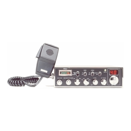
Galaxy DX 44V Manuel du propriétaire - Page 2
Parcourez en ligne ou téléchargez le pdf Manuel du propriétaire pour {nom_de_la_catégorie} Galaxy DX 44V. Galaxy DX 44V 9 pages. Full channel am/fm mobile transceiver

TABLE OF CONTENTS
Specification . . . . . . . . . . . . . . . . . . . . . . . . . . . . . . . . . . . .
Installation
Location . . . . . . . . . . . . . . . . . . . . . . . . . . . . . . . . . . . . .
Mounting the Radio . . . . . . . . . . . . . . . . . . . . . . . . . . . .
Ignition Noise Interference . . . . . . . . . . . . . . . . . . . . . .
Antenna . . . . . . . . . . . . . . . . . . . . . . . . . . . . . . . . . . . .
Tuning the Antenna for Optimum SWR . . . . . . . . . . . .
External Speaker . . . . . . . . . . . . . . . . . . . . . . . . . . . . . .
Operation
Control Functions . . . . . . . . . . . . . . . . . . . . . . . . . . . . .
A. Front Panel . . . . . . . . . . . . . . . . . . . . . . . . . . . . . . . .
B. Rear Panel . . . . . . . . . . . . . . . . . . . . . . . . . . . . . . . . .
Press-To-Talk Microphone . . . . . . . . . . . . . . . . . . . . . .
Operating Procedure to Receive . . . . . . . . . . . . . . . . . .
Operating Procedure to Transmit . . . . . . . . . . . . . . . . .
Alternate Microphones and Installation . . . . . . . . . . . .
Page
2
4
4
5
5
6
7
8
8
10
11
11
11
12
- 1 -
Specifications
GENERAL
Frequency Range
Frequency Control
Frequency Tolerance
Frequency Stability
Operating Temperature
Range
Microphone
Input Voltage
Size
Weight
Antenna Connector
Meter
TRANSMITTER
Power output
Modulation
Spurious Emissions
Frequency Response
Output Impedance
Output Indicators
28.315 to 28.755 MHz
Phase Lock Loop (PLL) synthesizer.
0.005%
0.001%
-30 °C to +50 °C.
Plug-in dynamic; with push-to-talk switch and
coiled cord.
13.8V DC nominal, 15.9V max, 11.7V min.
(Positive or negative ground).
Transmit: AM full mod., 2.2A.
Receiver: Squelched, 0.3A.
Maximum Audio output, 0.7A.
2-3/8" (H) x 7-7/8" (W) x 9-1/4" (D).
5 Ibs.
UHF, SO239
Illuminated; indicates relative output power,
received signal strength.
AM/FM, High-7 watts
High-and low-level Class B, Amplitude
Modulation:
AM.
Variable
Frequency Modulation: FM.
60 dB
AM and FM: 450 to 2500 Hz.
50 ohms, unbalanced
Meter shows relative RF output power and
SWR. Transmit LED glows red when
transmitter is in operation.
- 2 -
capacitance
