Galaxy DX−33HML Manuel du propriétaire - Page 7
Parcourez en ligne ou téléchargez le pdf Manuel du propriétaire pour {nom_de_la_catégorie} Galaxy DX−33HML. Galaxy DX−33HML 8 pages. Full channel am/fm mobile transceiver
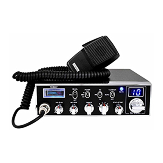
5. MODE (PA/FM/AM) SWITCH. This switch is used to select PA, FM, AM
mode of operation. The AM or FM mode is normally, but when you set to PA
position, the transceiver acts as a public address amplifier. Before operating
PA, you must first connect an external PA speaker (8 ohm, more than 2W) to
the PA Speaker jack on the unit rear panel.
6. BAND SELECTOR. This switch selects A, B, C, D, E, or F band of
operation.
7. ECHO. This control is used to echo effect.
8. TIME. This control is used to intervals of echo sound.
9. CHANNEL SELECTOR. This switch selects any one of the forty channels
desired. The selected channel appears on the LED readout directly above the
Channel Selector knob.
10. METER. This meter indicates received signal strength, transmitter RF output
power.
11. RF POWER. This switch is used to select transmitting power. In the HI
position, the transceiver operates in 7 watts RF output power. In the MED
position, the transceiver operates 4 watts RF output power. In the LO position,
the transceiver operates in 1 watts RF output power.
12. OFF/ANL/NB. When the switch is placed in the ANL+NB position, the RF
Noise Blanker also is activated. The RF Noise Blanker is very effective for
repetitive impulse noise such as ignition interference.
13. BAND SWITCH-HI/LOW. This switch is used to select High band and or
Low band Frequency Range.
14. OFF-ECHO SWITCH. This switch is used to add an echo effect to your
transmitting voice, when to ECHO position.
15. RECIEVER/TRANSMIT
indicator is located next to the channel indicator. When in receive, the LED
will be green. When in transmit the LED will be red.
16. CHANNEL INDICATOR. Numbered LED indicates the selected channel
you wish to operate on. LED indicates "9" when CH-9 is switched on.
INDICATOR.
The
receiver/transmit
- 9 -
TUNNING THE ANTENNA FOR OPTIMUM SWR
Since there is such a wide variety of base and mobile antennas, this section
will strictly concern itself to the various types of mobile adjustable antennas.
Because the antenna length is directly related to the channel frequency, it
must be tuned to resonate optimally all 40 channels of the transceiver. Channel 1
requires a longer antenna than Channel 40 because it is lower in frequency.
Due to the various methods of adjusting antennas for proper SWR we have
chosen what we think is the optimum method:
A. Antennas with adjustment screws (set screws)
1. Start with the antenna extended and tightens the set screw lightly enough so
that the antenna can be lightly tapped with your finger for easy adjustment.
2. Set your transceiver to Channel 21. @ Low band D or Hi band A. Press the
PTT (push-to-talk) switch, and tap the antenna (making it shorter). The SWR
meter will show a lower reading each time the antenna is tapped. By
continuing to shorten the antenna you will notice the SWR reading will reach a
low print and then start riding again. This means that you have passed the
optimum point for Channel 21. Extend the antenna a short distance and again
follow the procedure above.
When the lowest point has been reached, switch to Channel 1 @ Low band A
or Hi band A and then to Channel 40 @ Low band D or Hi band D and
compare SWR readings. They should be almost equal.
B. Antennas which must be cut to proper length.
1. Follow the same procedure as above, but adjust the length by cutting in 1/8"
increments until a good match is obtained.
2. Be very careful not to cut too much at one time, as one it is cut, it can no
longer be lengthed.
3. The whip is easily cut by filing a notch all the way around and breaking the
piece off with pliers.
THE PROPER SETTING IS ACHIEVED WHEN THE SWR IS
1.5 OR BELOW, AND WHEN IT HAS THE SAME READING
FOR CHANNELS LOW BAND A1 AND HI BAND D40.
LED
If you are having difficulties in adjusting your antenna, check the following:
A. All doors must be closed when adjusting the antenna.
B. Make sure the antenna base is grounded.
C. Check your coaxial cable routing (it may be pinched when routed into the
car).
NOTE
- 6 -