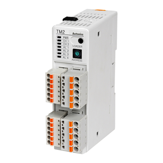
Autonics TM2-22RB Manuel de l'utilisateur - Page 6
Parcourez en ligne ou téléchargez le pdf Manuel de l'utilisateur pour {nom_de_la_catégorie} Autonics TM2-22RB. Autonics TM2-22RB 9 pages. Tm series

Input sensor type and temperature range
Input●sensor
K(CA)●●
J(IC)●
E(CR)●●
●T(CC)
B(PR)●●
Thermocouple
R(PR)●●
S(PR)●●
N(NN)●●
※ 1●
C(TT)
※ 2
G(TT)
L(IC)●●
U(CC)●●
Platinel●II●●
●JPt●100Ω●●
RTD
DPt●100Ω●●
※
1:●C(TT):●Same●as●existing●W5(TT).●
※
Default:●K(CA).H
Error indication
●●
PWR●LED●●●●
CH1●LED●●●●
CH2●LED●●●●
※ 1●
CH3●LED
※ 1
CH4●LED●
Communication●output●(decimal)
Dedicated●program
※ 1:●Only●for●TM4●Series(4CH).●
Communication setting
A●function●for●external●parameter●setting●&●monitoring●with●PC●or●PLC.
● Interface
Application●Standard
Compliance●with●EIA●RS●485
31●units
Max.●connection
(communication●address●setting:●01●to●31)
Communication●type
Two●wire,●Half●Duplex
Synchronization●method Asynchronous
Communication●distance Max.●800m
Communication●
2400,●4800,●9600(default),19200,●38400
speed(bps)
Communication●
5●to●99ms
response●time
Start●Bit
1bit(fixed)
Stop●Bit
1bit,●2bit(default)
Parity●Bit
None(default),●Odd,●Even
Data●Bit
8bit(fixed)
Protocol
Modbus●RTU
※ Overlapped●address●setting●is●not●allowed●on●the●same●
communication●line.●Twisted●Pair●wires(for●RS485●communication)●
must●be●used●for●communication●cable.
Multi-Channel Module type PID Control
No.
Dot
Display
0
1
K(CA).H
1
0.1
K(CA).L
2
1
J(IC).H
3
0.1
J(IC).L
4
1
E(CR).H
5
0.1
E(CR).L
6
1
T(CC).H
7
0.1
T(CC).L
8
1
B(PR)
9
1
R(PR)
10
1
S(PR)
11
1
N(NN)
12
1
C(TT)
13
1
G(TT)
14
1
L(IC).H
15
0.1
L(IC).L
16
1
U(CC).H
17
0.1
U(CC).L
18
1
PLII
19
1
JPt100.H
20
0.1
JPt100.L
21
1
DPt100.H
22
0.1
DPt100.L
※
●●●●●●●●●●●●●●●●●●●
2:●G(TT):●Same●as●existing●W(TT).
Input●sensor●open●error
Red●ON
RED●Flashing●(for●0.5●sec.)
RED●Flashing●(for●0.5●sec.)
RED●Flashing●(for●0.5●sec.)
RED●Flashing●(for●0.5●sec.)
'31000'●output
'OPEN'●indication
Input●range●( ℃ )
-200●to●1350
-200.0●to●1350.0
-200●to●800
-200.0●to●800.0
-200●to●800
-200.0●to●800.0
-200●to●400
-200.0●to●400.0
0●to●1800
0●to●1750
0●to●1750
-200●to●1300
0●to●2300
0●to●2300
-200●to●900
-200.0●to●900.0
-200●to●400
-200.0●to●400.0
0●to●1400
-200●to●600
-200.0●to●600.0
-200●to●600
-200.0●to●600.0
Over●temperature●range
'30000●(upper●limit)'●output,●'-30000●(lower●limit)'●output
'HHHH●(upper●limit)'●indication●,●'LLLL●(lower●limit)'●indication
● Communication speed indication
Current●communication●speed●will●be●flashing●in●
case●of●initial●power●ON●for●5●sec.●(1●sec.●cycle).
※ One●module●communication●is●allowed●for●Port●A.
●●●●Communication●speed●is●fixed●to●9600bps.
※ Multiple●communication●is●allowed●for●Port●B.●It●is●required●to●
reset●controller's●Power(Power●OFF→Power●ON)●after●changing●
communication●speed.
※ Simultaneous●monitoring●can●not●be●done●for●Port●A●and●B●since●
Port●A●is●for●parameter●setting●only.
※ If●connects●communication●through●Port●A,●Port●B●will●be●
disconnected●communication●automatically.
(A)
Photo
electric
Input●range●( ℉ )
sensor
-328●to●2462
(B)
Fiber
-328.0●to●2462.0
optic
sensor
-328●to●1472
-328.0●to●1472.0
(C)
Door/Area
sensor
-328.0●to●1472
-328.0●to●1472.0
(D)
Proximity
-328●to●752
sensor
-328.0●to●752.0
32●to●3272
(E)
Pressure
sensor
32●to●3182
32●to●3182
(F)
Rotary
-328●to●2372
encoder
32●to●4172
32●to●4172
(G)
Connector/
Socket
-328●to●1652
-328.0●to●1652.0
(H)
-328●to●752
Temp.
controller
-328.0●to●752.0
(I)
32●to●2552
SSR/
Power
-328●to●1112
controller
-328.0●to●1112.0
(J)
-328●to●1112
Counter
-328.0●to●1112.0
(K)
Timer
(L)
Panel
meter
(M)
Tacho/
Speed/ Pulse
meter
(N)
Display
unit
(O)
Sensor
controller
(P)
Switching
mode power
supply
(Q)
Stepper
motor&
Driver&Controller
(R)
Graphic/
Logic
panel
(S)
Field
network
device
(T)
Software
(U)
Other
H-15
