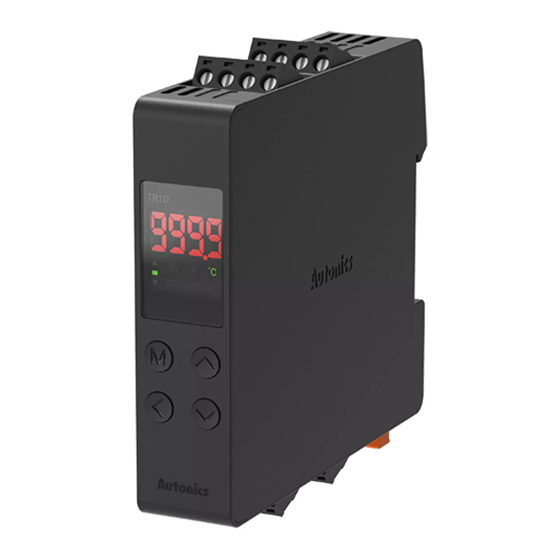
Autonics TR1D-14RR Manuel - Page 4
Parcourez en ligne ou téléchargez le pdf Manuel pour {nom_de_la_catégorie} Autonics TR1D-14RR. Autonics TR1D-14RR 6 pages. Independent single display pid temperature controllers

Installation Method
■ Mounting on DIN rail
• Mount the metal part with a spanner so that a large force is not applied to the body.
Install
①
②
1. Hang the top of backside holder to 35
mm width DIN rail.
2. Press the unit in the direction of the
arrow until there is clicking sound.
Attaching and Dettaching a Terminal Unit
■ Detaching
ⓐ
Lift the lower part of the terminal unit ⓐ
upwards by using a tool (e.g. flat-head
driver).
• When disconnecting terminal unit and wiring, refer to 'Connections' to attach to
right position. Failure to follow this instruction may result in fire product damage or
malfunction.
Mode Setting
Display part
→
[▲] key over 2 sec
switching
No key input over
→
screen protection
protection
time
[▼] + [▲] key over 3
Digital input key
→
RUN
sec
[MODE], [◀], [▲] or
→
SV setting
[▼] key
Parameter
[MODE] key over 2
→
sec
[◀] + [▲] + [▼] key
→
Parameter reset
over 3 sec
Uninstall
②
①
1. Pull the bracket handle on the bottom
of the unit in the direction of the arrow.
2. Lift the unit up while pulling the handle
bracket to remove.
■ Attaching
Press the terminal unit downwards to
insert.
Auto
Screen
[MODE], [◀], [▲], [▼] key
Auto
[MODE] key or no key
input over 3 sec
[MODE] key over 2 sec
group
Auto
Parameter Setting
• Some parameters are activated/deactivated depending on the model or setting of
other parameters. Refer to the descriptions of each item.
• Select group by [▲], [▼] key and press [MODE] key to parameter setting mode in
parameter group setting mode.
• [MODE] key: Move to next item after saving / Return to upper level with save (≥ 2 sec)
[◀] key: Move digits / Return to the upper level without saving (≥ 2 sec) / Return to
RUN mode without saving (≥ 3 sec)
[▲], [▼] key: Select parameter / Change setting value
• Return to the upper level without saving when there is no key input for more than 30
seconds.
• The range in parentheses '( )' is the setting range when the set value of the 'input
specification' parameter is used with one decimal point.
• Recommended parameter setting sequence: Parameter 2 group → Parameter 1 group
→ SV setting mode
■ Parameter 1 group
Parameter
Display Default Setting range
1-1
Lock
Heater
1-2
current
monitoring
1-3
Auto tuning
AL1 alarm
1-4
temperature
AL2 alarm
1-5
temperature
Heating
1-6
proportional
band
Heating
1-7
integral time
Heating
1-8
derivative
time
Cooling
1-9
proportional
→
band
Cooling
1-10
integral time
Cooling
→
1-11
derivative
time
→
RUN
1-12 Dead band
01)
→
→
1-13 Manual reset
→
Heating
1-14
hysteresis
Heating OFF
1-15
offset
Cooling
1-16
hysteresis
Cooling OFF
1-17
offset
01) When set to the + value, the dead band is formed based on SV and does not control any control.
When set to the - value, the overlap band is formed based on SV, perform the heating and cooling control at the
same time.
02) Parameter display following to the setting value of '2-8 Control output mode'
HEAT: '1-14 & 15 Heating hysteresis & OFF offset'
COOL: '1-16 & 17 Cooling hysteresis & OFF offset'
H-C: '1-14 & 15 Heating hysteresis & OFF offset', '1-16 & 17 Cooling hysteresis & OFF offset'
OFF
LOC1: Lock parameter 2 group
LOC2: Lock parameter 1, 2 group
LOC3: Lock parameter 1, 2 group
LOCK
OFF
+ SV setting lock
• It is possible to check the value only in
lock mode.
[CT input model]
0.0 to 50.0 A
CT-A
-
OFF OFF, ON: Execution
AT
Deviation alarm: -F.S. to F.S. ℃/℉
Absolute value alarm: Within input
AL1
1250
• Changing the '2-16/19 AL1/2 alarm
operation' and '2-17/20 AL1/2 alarm
option' will automatically reset the
value to the maximum or minimum
AL2
1250
that will not be output.
10 0.1 to 999.9 ℃/℉
H-P
240 0 (OFF) to 9999 sec
H-I
49 0 (OFF) to 9999 sec
H-D
10 0.1 to 9999 ℃/℉
C-P
240 0 (OFF) to 9999 sec
C-I
49 0 (OFF) to 9999 sec
C-D
-Proportional band to +Proportional
band ℃/℉
DB
0
-999 to 999 (-199.9 to 999.9) ℃/℉
50 0.0 to 100.0%
REST
2 1 to 100 (0.1 to 100.0) ℃/℉
hHYS
0 0 to 100 (0.0 to 100.0) ℃/℉
hOST
2 1 to 100 (0.1 to 100.0) ℃/℉
cHYS
0 0 to 100 (0.0 to 100.0) ℃/℉
cOST
Condition
-
2-10/11
Control
output 1/2:
SSR
2-9 Control
type: PID
2-16/19
specification
AL1/2 alarm
operation:
AM1 to AM6,
HBA
-
-
-
-
-
-
2-9 Control
type: P.P,
P.ON, ON.P
2-9 Control
type: ON.ON
1-7/10
Heating/
Cooling
integral time:
0
2-9 Control
type: ONOF
&
2-8 Control
output mode
02)
