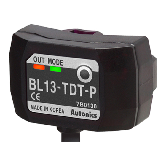
Autonics BL13-TDT-P Manuel d'instruction - Page 2
Parcourez en ligne ou téléchargez le pdf Manuel d'instruction pour {nom_de_la_catégorie} Autonics BL13-TDT-P. Autonics BL13-TDT-P 4 pages. Liquid level sensor for mounting pipe (through-beam)

Operation Mode
Absent liquid (light on)
Present liquid (dark on)
Operating Timing Diagram
Stable light ON area
High
Incident
Unstable operation level
light
level
Stable light OFF area
Low
Operation
indicator
OFF
(red LED)
Light ON
Transistor
output
OFF
※ The waveforms of 'Operation indicator' and 'Transistor output' are for Light ON, it is operated as reverse in Dark ON.
Control Output Circuit Diagram
Sensor circuit
NPN
open
collector
Output short
output
overcurrent
protection circuit
Output short
PNP
overcurrent
protection circuit
open
collector
output
※ I fshort-circuitthecontroloutputterminalorsupplycurrentovertheratedspecification,
normalcontrolsignalisnotoutputduetotheoutputshortovercurrentprotectioncircuit.
Operation mode
Receiver operation
Operation indicator
(red LED)
Transistor output
Operation mode
Receiver operation
Operation indicator
(red LED)
Transistor output
ON
ON
Connection
(brown)+V
Load
(black)Output
Max. 100mA
(blue)0V
(brown)+V
(black)Output
Load
(blue)0V
Liquid Level Sensor
Light ON
Received light
Interrupted light
ON
OFF
ON
OFF
Dark ON
Received light
Interrupted light
ON
OFF
ON
OFF
Operation
level
Connection
+
12-24VDC
-
0V
+
12-24VDC
-
① Load connection for PNP output
② Load connection for NPN output
(blue)
(black)
(brown)
Output
+V
Load
Load
-
+
12-24VDC
SENSORS
CONTROLLERS
MOTION DEVICES
SOFTWARE
(A)
Photoelectric
Sensors
(B)
Fiber Optic
Sensors
(C)
LiDAR
(D)
Door/Area
Sensors
(E)
Vision
Sensors
(F)
Proximity
Sensors
(G)
Pressure
Sensors
(H)
Rotary
Encoders
(I)
Connectors/
Connector Cables/
Sensor Distribution
Boxes/ Sockets
A-141
