dbx SC 64 Manuel d'installation - Page 13
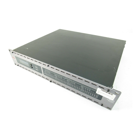
Parcourez en ligne ou téléchargez le pdf Manuel d'installation pour {nom_de_la_catégorie} dbx SC 64. dbx SC 64 20 pages. Digital matrix processors

SC 32 / SC 64
SC 32 / SC 64
OPTO Output
In addition to the six standard logic outputs, there is an isolated output, which fails safe
(open circuit) if the unit becomes faulty.
C
Logic Outputs
Used to connect 'tally' indicator LED's or relays. There are six standard LOGIC OUTPUTS which
produce 0V or +5V DC via an internal 440 Ohm resistor and one internally connected common
(ground) connection C. Each logic output pin can sink up to 60mA.
An LED connected between one output (Anode, A) and common (Cathode, K) will illuminate
when the logic output is activated, without requiring any external current limiting resistor.
A high sensitivity relay (such as a reed relay) may be driven by connecting four outputs in
parallel. This arrangement will develop 4V across a 500-Ohm coil, providing that all four
outputs are made logic 1 simultaneously.
C
®
+supply
CONTROL INPUTS
RELAY
C
1
2 3 4 5 6
7
8 R R
NO
C
NC
ground
OPTO Output
CONTROL INPUTS
RELAY
OPTO
+
C
1
2 3 4 5 6
7
8 R R
NO
C
NC
Logic Outputs
OPTO
LOGIC OUTPUTS
+
-
C 1 2 3 4 5 6
LOGIC OUTPUTS
-
C 1 2 3 4 5 6
LED
relay
Section 3
Wiring
9
