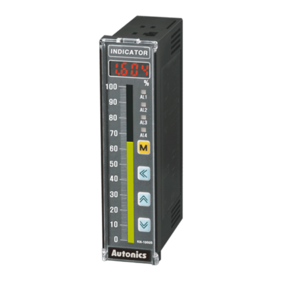
Autonics KN-1000B Series Manuel du produit - Page 5
Parcourez en ligne ou téléchargez le pdf Manuel du produit pour {nom_de_la_catégorie} Autonics KN-1000B Series. Autonics KN-1000B Series 6 pages. Bar graphic temperature indicators

Function: Bar Graph
■ Display method setting
It is possible to set in bar graph display method parameter.
Full bar
100
Displays the input from
the bottom for bar graph
scale following to bar
graph display scale
0
parameter setting value
• L-BS= 100, H-BS= 100,
-50
PV = 50
-100
← Bottom
■ Alarm display in bar graph
When setting or occurring the alarm, it displays the status by the bar graph. It is possible
to check the alarm status. When setting alarm value, the bar LED for this alarm value
turns ON. When alarm occurs, the bar LED for this alarm value flashes.
• If alarm set value is out of bar graph scale when setting the value or in RUN mode, this
value does not display in bar graph.
Monitoring mode: setting alarm value
The bar LED for alarm setting value flashes.
When alarm set is complete, the bar LED
for this alarm value turns ON.
• The bar LED for the alarm value flashes.
■ Scale value relation
Below is relation example of input specification, high/low limit input, high/low limit
scale, bar graph display high/low limit scale, 4/20 mA transmission output scale when
using 4 to 20 mA input specification.
Refer to 'Parameter Setting' for the details about setting range and condition.
Input specification
High/Low limit input
High/Low limit scale
Bar graph display
high/low limit scale
4/20 mA transmission
output scale
Center bar
100
Displays the input from zero
point (0) for bar graph scale
following to bar graph display
scale parameter setting value
0
← Zero point
• L-BS= 100, H-BS= 100,
-50
PV = 50
-100
Run mode: alarm display
All set alarm values are displays and
when it is alarm value, the bar LED for this
alarm value flashes.
• AL1/2:
• AL3/4:
Low limit alarm
High limit alarm
Function: Input Special Function
When selecting analog input, this function is to display the calculated actual value by
square, root (√), or two unit function (TUF) as display value.
Name
Function
Graph
Display
Outputs as input
Linear
value
Display
Outputs the
Root
rooted (√) input
value
Output={(
Display
Outputs the
Square
squared input
value
Output={(
6.00
Display the
4.00
pressure
of under
2.00
atmospheric
pressure (0) as
-1.03
Two unit
mmHg unit
-760 mmHg
• Compound pressure input <
• Compound pressure input ≥
Atmospheric pressure is based on 0 kg/cm
be calibrated by using the 'Digital input: zero-point adjustment' function and
additionally adjusted by using the 'Input correction' function.
Function: Input Digital Filter
Moving average digital filter is able to stably display and output the noise from input
line and irregular signals as software.
• Display cycle is same when executing moving average digital filter.
100 ms
S1
S2
S3
S4
D1
D2
D3
D4
D1=S1, D2=S2, D3=S3: Initial operation before averaging 4
S1+S2+S3+S4
D4=
4
S3+S4+S5+S6
D6=
4
S5+S6+S7+S8
D8=
4
Applications
Y = AX + B
Standard
characteristics. Input
for linearity.
Input
Y = A( X ) + B
(X ≥ 0)
Used for measuring
flows by pressure
Y=0(X < 0)
signal.
Input
Input - L-RG
2
) × (H-SC-L-SC)} + L-SC
H-RG - L-RG
Y = A(X)
+ B
2
(X > 0)
Used for outputting
differential pressure
Input
by flow signal.
Y = -A(X)
+ B
2
(X < 0)
Input - L-RG
) × (H-SC - L-SC)} + L-SC
H-RG - L-RG
Display (kg/cm
)
2
-
2.00 4.00
6.00
Input
(kPa)
Display (mmHg)
atmospheric pressure
: Displayed in mmHg
atmospheric pressure
: Displayed in kg/cm
. Atmospheric pressure value can
2
S5
S6
S7
S8
S9
Sn: Sampling value
Dn: Display value
D5
D6
D7
D8
S2+S3+S4+S5
D5=
4
S4+S5+S6+S7
D7=
4
2
