Galaxy Audio BE HEARD PSE Manuel de démarrage rapide
Parcourez en ligne ou téléchargez le pdf Manuel de démarrage rapide pour {nom_de_la_catégorie} Galaxy Audio BE HEARD PSE. Galaxy Audio BE HEARD PSE 2 pages.
GAL A X Y AUDIO
Wireless Microphone System
Included Components
1.
1.
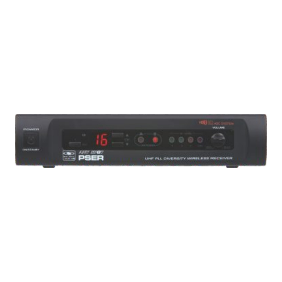
PSER x1
2.
Antennas x2
3.
MREWD Rack Kit x1
2.
4.
Antenna Plugs x2
5.
1/4" to 1/4" Audio Cable x1
6.
3.
Power Supply x1
7.
Quick Start Guide x1
Setup
1
Insert the 5.5 mm plug into the DC
input jack, then plug the wall wart into a
120VAC outlet.
Dual Rack Mounting
(Optional)
1
Screw 1 short rack ear on the left side of
the first receiver, and 1 coupler half onto
the right side using the provided screws.
Screw 1 short rack ear on the right side
of the second receiver, and 1 coupler half
onto the left side of the same receiver.
3
Then press ASC on the receiver. The
Receiver IR Window Location is located
on the left of the receiver face
7.
GAL A X Y AUDIO
Wireless Microphone System
Included Components
1.
1.
PSER x1
2.
Antennas x2
3.
MREWD Rack Kit x1
2.
4.
Antenna Plugs x2
5.
1/4" to 1/4" Audio Cable x1
6.
Power Supply x1
3.
4.
7.
Quick Start Guide x1
Setup
1
2
Insert the 5.5 mm plug into the DC
XLR Output: Connect a shielded
input jack, then plug the wall wart into a
microphone cable to the receiver's AF
120VAC outlet.
XLRM output, then connect the other
5.
end into your mixer input.
Dual Rack Mounting
(Optional)
1
2
Screw 1 short rack ear on the left side of
Align both receivers so that the coupler
the first receiver, and 1 coupler half onto
halves fit, and screw them together.
the right side using the provided screws.
Screw 1 short rack ear on the right side
of the second receiver, and 1 coupler half
onto the left side of the same receiver.
3
4
Then press ASC on the receiver. The
Place the chosen transmitter with it's IR
Receiver IR Window Location is located
window facing the receiver IR window,
on the left of the receiver face
6" away. Handheld IR is located inside
4.
6.
the battery compartment. Body Pack IR
is located on the backside bottom corner.
2
XLR Output: Connect a shielded
microphone cable to the receiver's AF
XLRM output, then connect the other
end into your mixer input.
2
Align both receivers so that the coupler
halves fit, and screw them together.
4
Place the chosen transmitter with it's IR
window facing the receiver IR window,
6" away. Handheld IR is located inside
the battery compartment. Body Pack IR
is located on the backside bottom corner.
For detailed instructions for finding the best frequencies, please consult the online manual.
Optional Accessories
Q uick Start Guide
PSE
Optional Accessories
What May be Needed
7.
1.
1.
HH52 Handheld Mic
to Rack
2.
MBP52 Body Pack
(Not Included)
1.
5.
3.
HS-U3BK Headset Mic
HH52 Handheld Mic
4.
LV-U3BK Lav Mic
2.
3.
4.
1.
Rack Screws 10/32 x .75",
Phillips Truss Head Screws
5.
AS-GTR Guitar Cable
2.
6.
#2 Phillips Head
Screwdriver
5.
1.
2.
Single Rack Mounting
(Optional)
2.
MBP52 Body Pack
3
4
1
1/4" Output: Connect 1 end of a shielded
Attach the antennas to the antenna jacks
Attach the long and short rack ears to
1/4"M to 1/4"M cable to the receiver's
on the receiver.
either side of choice using the provided
1/4" output, then connect the other
screws. Align and screw into the rack.
3.
end into your system input.
HS-U3BK Headset Mic
Operation
3
1
2
4.
LV-U3BK Lav Mic
Align the dual receivers to the rack and
Power on the receiver. Press the "CH."
To sync the handheld mic transmitter,
screw into the rack.
up or down buttons on the receiver to
make sure to power on first. For the body
choose a frequency number of 1-16.
pack, power on and then press the ASC
button.
5
6
7
5.
AS-GTR Guitar Cable
When the transmitter is synced, the AF
Use the level control to adjust the
The Mute Level is factory set and
Level and Antenna indication will light up.
volume. This will affect both the XLR
normally needs no adjustment. However,
When talking into the microphone the AF
and 1/4" outputs.
you may turn clockwise if interference is
presence indicator will illuminate.
present.
For detailed instructions for finding the best frequencies, please consult the online manual.
3
1/4" Output: Connect 1 end of a shielded
1/4"M to 1/4"M cable to the receiver's
1/4" output, then connect the other
end into your system input.
3
Align the dual receivers to the rack and
screw into the rack.
5
When the transmitter is synced, the
Antenna indication will light up. When
talking into the microphone the AF level
indicators will illuminate.
1.
2.
3.
4.
5.
4
Attach the antennas to the antenna jacks
on the receiver.
Operation
1
Power on the receiver. Press the "CH."
up or down buttons on the receiver to
choose a frequency number of 1-16.
6
Use the level control to adjust the
volume. This will affect both the XLR
and 1/4" outputs.
Quick Start Guide
PSE
What May be Needed
to Rack
(Not Included)
1.
Rack Screws 10/32 x .75",
Phillips Truss Head Screws
2.
#2 Phillips Head
Screwdriver
1.
2.
Single Rack Mounting
(Optional)
1
Attach the long and short rack ears to
either side of choice using the provided
screws. Align and screw into the rack.
2
To sync the handheld mic transmitter,
make sure to power on first. For the body
pack, power on and then press the ASC
button.
7
The Mute Level is factory set and
normally needs no adjustment. However,
you may turn clockwise if interference is
present.