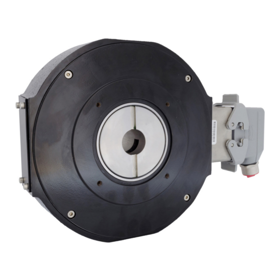
DYNAPAR NorthStar NexGen RIM Tach HT85 Manuel d'installation - Page 4
Parcourez en ligne ou téléchargez le pdf Manuel d'installation pour {nom_de_la_catégorie} DYNAPAR NorthStar NexGen RIM Tach HT85. DYNAPAR NorthStar NexGen RIM Tach HT85 7 pages.

INSTALLATION
1.0 MECHANICAL INSTALLATION
The RIM Tach® HT85 is shipped partially assembled.
There are no field gap checks, axial alignment, or
run out checks required. Sensor Module shimming
may be required. The interchangeable stainless steel
sensor modules are available in a wide variety of
pulse counts. After unpacking the unit and verifying
receipt of the items listed on the packing list, proceed
with mechanical installation.
1. Place an anti-seizing agent such as a light moly-
grease or other high temperature, stable corrosion
inhibitor on motor shaft. This will aid not only
installation but future removal of the encoder for
maintenance, repairs, etc., and lessens chances for
corrosion.
2. Slide encoder housing onto motor shaft with flange
surface (back side-see Figure 2) facing the motor,
and tilted so the sensor head is facing downward. In
this orientation, the B channel will lead the A channel
when shaft rotation is CCW.
Figure 1: Encoder Housing Orientation
3. Remove black, trapezoidal access plate from the
encoder housing using an M4 (DIN 912) metric hex
wrench. Once removed, the clamping ring segment is
now available for tightening.
NOTE: Dual units require a hex wrench to remove
a module.
Page 4
4. Tighten the clamping ring segment as follows (see
Figure 2):
1) Look inside the access plate hole and rotate
the hollow shaft until the two M5-0.8x12 mounting
screw heads on clamping ring are visible.
2) Being very careful not to damage the magnetic
pulse wheel (see Figure 2 below), tighten down
both mounting screws using the M4 T-Handle hex
wrench (included). Torque each mounting screw to
55 in-lbs (6.3 N-M regular) nominal, while ensuring
gaps on both radial ends of clamping ring segment
are approximately equal.
IMPORTANT: Be very careful not to touch the
pulse ring when tightening the cap screws.
The pulse ring is near the screws and can be
damaged easily. The magnetic properties of the
pulse wheel material can also be distorted or
erased by exposure to strong magnetic fields.
IMPORTANT: Do not unscrew the (2) cap screws
on the clamp ring completely, either when un-
installing or servicing the encoder. The screws
may fall inside the unit and would be difficult to
retrieve.
Figure 2: Clamping Ring Segment
5. Reinstall the access plate back onto encoder
housing, or place second sensor module assembly.
6. Attach/insert anti-rotation arm into the threaded
hole (3/8"-24 UNF) in the encoder housing (see
Figure 3). Complete approximately 10 turns of
the anti-rotation arm into stud. Tighten locking nut
(using a 9/16" open wrench) against the encoder
housing.
