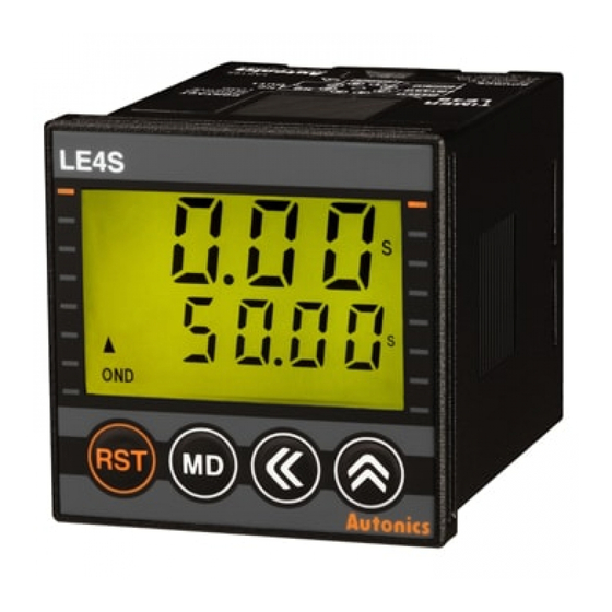
Autonics LE4S Series Manuel
Parcourez en ligne ou téléchargez le pdf Manuel pour {nom_de_la_catégorie} Autonics LE4S Series. Autonics LE4S Series 6 pages. Lcd digital timers
Également pour Autonics LE4S Series : Instruction (18 pages), Manuel (17 pages)

DRW210103AA
LCD Digital Timers
LE4S Series
For your safety, read and follow the considerations written in the instruction
manual, other manuals and Autonics website.
The specifications, dimensions, etc. are subject to change without notice for product
improvement. Some models may be discontinued without notice.
Features
• Mounting space saving with compact design
: downsized by approx. 22% in depth compared to existing models (length of panel on
the back side is 56 mm)
• Available to set each value and time range separately when choosing Flicker (FK, FK I)
or ON-OFF Delay (ON OFF D, ON OFF D I) output mode
• Adds Flicker 1 mode (LE4SA)
• Settable One-shot output time (0.01 to 99.99 sec) (existing model: fixed 0.5 sec)
• Configurable time range (added 9.999 sec): settable by 0.001 sec unit
• Selectable min. input time: 1 ms or 20 ms (LE4S)
• Improved return time: 100 ms
• Backlight ON / OFF function
• Wide time range (0.01 sec to 9999 hour)
• Lock setting function for saving setting data
• Soft touch setting
• High visibility display with backlight
ᜢ ᜧ ᜫ
Safety Considerations
• Observe all 'Safety Considerations' for safe and proper operation to avoid hazards.
• symbol indicates caution due to special circumstances in which hazards may occur.
Warning
Failure to follow instructions may result in serious injury or death.
01. Fail-safe device must be installed when using the unit with machinery that
may cause serious injury or substantial economic loss. (e.g. nuclear power
control, medical equipment, ships, vehicles, railways, aircraft, combustion
apparatus, safety equipment, crime/disaster prevention devices, etc.)
Failure to follow this instruction may result in personal injury, economic loss or fire.
02. Do not use the unit in the place where flammable/explosive/corrosive gas,
high humidity, direct sunlight, radiant heat, vibration, impact or salinity
may be present.
Failure to follow this instruction may result in explosion or fire.
03. Install on a device panel to use.
Failure to follow this instruction may result in fire or electric shock.
04. Do not connect, repair, or inspect the unit while connected to a power
source.
Failure to follow this instruction may result in fire or electric shock.
05. Check 'Connections' before wiring.
Failure to follow this instruction may result in fire.
06. Do not disassemble or modify the unit.
Failure to follow this instruction may result in fire or electric shock.
Caution
Failure to follow instructions may result in injury or product damage.
01. When connecting the power/sensor input and relay output, use AWG 20
(0.50 mm
) cable or over, and tighten the terminal screw with a tightening
2
torque of 0.74 to 0.90 N m.
Failure to follow this instruction may result in malfunction due to contact failure.
02. Use the unit within the rated specifications.
Failure to follow this instruction may result in fire or product damage.
03. Use a dry cloth to clean the unit, and do not use water or organic solvent.
Failure to follow this instruction may result in fire or electric shock.
04. Keep the product away from metal chip, dust, and wire residue which flow
into the unit.
Failure to follow this instruction may result in fire or product damage.
Cautions during Use
• Follow instructions in 'Cautions during Use' .
Otherwise, it may cause unexpected accidents.
• When supplying or turning off the power, use a switch or etc. to avoid chattering.
• Install a power switch or circuit breaker in the easily accessible place for supplying or
disconnecting the power..
• In order to block peripheral current, use isolation transformer which of secondary part
is not grounded to supply power to the external input device.
START
RESET
INHIBIT
Sensor
Sensor power
Rectification
Insulation
circuit
transformer
• Do not connect two or more timers with only one input contact or transistor
simultaneously.
• Keep away from high voltage lines or power lines to prevent inductive noise. In case
installing power line and input signal line closely, use line filter or varistor at power line
and shielded wire at input signal line.
Do not use near the equipment which generates strong magnetic force or high
frequency noise.
• This unit may be used in the following environments.
- Indoors (in the environment condition rated in 'Specifications')
- Altitude max. 2,000 m
- Pollution degree 2
- Installation category II
Power
supply
