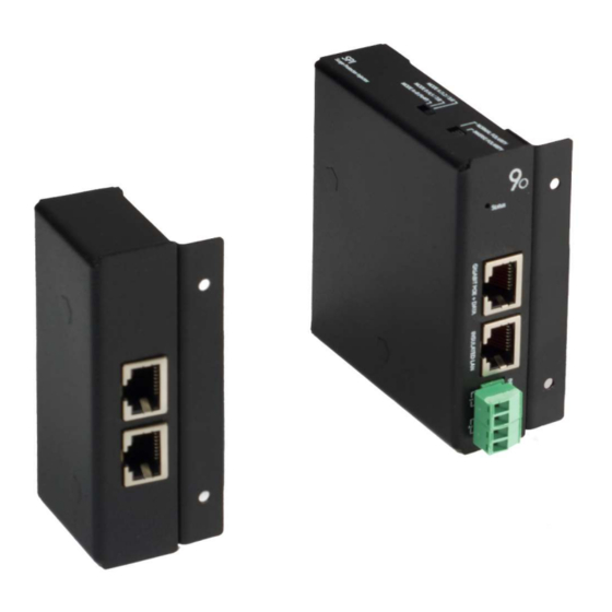
9dot SPMS SPI Manuel - Page 9
Parcourez en ligne ou téléchargez le pdf Manuel pour {nom_de_la_catégorie} 9dot SPMS SPI. 9dot SPMS SPI 15 pages.

Technical specifications
Product code
Operating voltage [V]
Main power connector
Active protection
Self-consumption power [W]
Typical current per port [A] (*)
GND connector
LED indicator
Peak current protection [kA]
Overvoltage protection [V]
Protection mode
SPD technology
Ethernet connector
Network transmission speed
Dimensions (LxPxH) [mm]
Weight [gr]
Material
Mounting
Operating ambient temperature [° C]
Operating humidity without condensation [%]
IMPORTANT NOTES:
•
(*) Although the typical value indicates that 0.7A current can flow continuously and indefinitely, this value must not
be exceeded.
•
(*) The typical current of 0.7A per port can be reached if the PoE configuration chosen to power a device is MODE A
+ B because it uses all four pairs of conductors for power supply
port will be 0.35A.
See the section "Selectors"
2
SPI & SPP MANUAL
SPI MODULE
ELECTRICAL SPECIFICATIONS
Against polarity inversion on both power connectors
All the lines (1-8) Protected (L-L) and (L-G)
NETWORK SPECIFICATIONS
2 x Jack RJ45 shielded (LAN / PoE + Data)
MECHANICAL SPECIFICATIONS
On rack (with optional Rack bracket) or Din rail (with optional Din clip)
ENVIRONMENTAL SPECIFICATIONS
SPI
Clamps: +/- 10 to 60 AC/DC
2 x cable terminals 2 x 1.31 mm
< 1.5
0.7
Screw M4
Status
15
150
2 phases: TVS and GDT
10BaseT; 100BaseT; 1000BaseT
87 x 84 x 24 (36 with flange)
200
Varnished iron
-20 to +45
5 to 95
. If it is MODE A or MODE B, the typical current per
2
9
2
VER. 2 REV. 0
