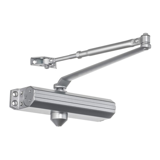
Dynasty DYN-1614 Instructions d'installation - Page 2
Parcourez en ligne ou téléchargez le pdf Instructions d'installation pour {nom_de_la_catégorie} Dynasty DYN-1614. Dynasty DYN-1614 2 pages.

REGULAR ARM (PULL SIDE)
Hinge
Speed Regulating
Valves
A
Dimension"A"
Opening Angle
Inch
mm
7
178
TO 100°
6
*101° TO 120°
152
3-1/2
89
*OVER 120°
* Recommended mounting for meeting ADA compliance
* When door closer is installed and adjusted to conform to ADA
reduced opening force requirements (5 lbs max.), it may not have
adequate closing force to reliably close and latch the door.
Door Frame
Position of arms and index settings
Door Leaf
Fig. A
Pinion flat
Power size and backcheck adjustment
Adjust the spring power as per chart on page 1. DO NOT
exceed the maximum turns.The spring power has been
preset at size 3 from factory.Turn this screw clockwise to
increase or counter-clockwise to decrease power.
Power adjustment Nut.
Turn BC regulating valve
BC
clockwise to strengthen or
counter clock-
wise to reduce the intensity.
NEVER close this valve
completely.
Improper installation may result in personal injury or property damage.
!
Caution
Follow all instructions carefully please.
2
Foot
6
1-3/4
(152)
(44)
1
(26)
Arm screw
1-1/4
(32)
BC
3/4
(19)
9-1/16
Pinion Cap
(230)
Right hand door illustrated
Same dimensions apply to left hand door.
Measured from hinge Center.
Dimensions are in inches
(mm)
Not To Scale
INSTALLATION STEPS:
1. Select degree of opening and use dimensions
shown or attached template to locate 4 holes on
door for closer body and 2 holes on frame face for
forearm shoe.
2. Prepare door and frame for fasteners. See
"Preparation for Fasteners", Figure 1, Page 1.
3. Before installing closer body, adjust spring power
for closer using Power adjustment chart,Page 1.
4. Disassemble forearm from main arm by removing
Fig. B
elbow washer and screw.
5. Mount main arm onto closer pinion shaft, aligning
arm mark "S"with pinion flat (see Fig.A) secure with
main arm screw and washer.
6. Attach the closer body to door leaf with speed
regulating valves toward hinge .
7.Attach the foot of rod to the door frame.
8.Adjust length of the forearm to position the forearm at
90 ° to the door frame when connected to
main arm at elbow (See Fig.B).
Use washer and screw provided to secure pivot
connection.Tighten the locknut on forearm.
9.Snap the pinion cap over spindle at the bottom of
closer.
Position of main arm
10.Adjust closer.
when assembled to spindle.
Sweep, Latching and Delayed action adjustment
Turn speed regulating valve clockwise to slow down
or counter clockwise to speed up door movement.
L
S
Latching
Sweep
Delayed Action*
speed
speed
(*Optional)
Pinion Cap
Door
BC
Frame
Door
Arm screw
Leaf
Foot
Right hand door illustrated
same dimensions apply to left hand door.
Measured from hinge Center.
Dimensions are in inches
(mm)
Not To Scale
INSTALLATION STEPS:
1. Select degree of opening and use dimensions
shown or attached template to locate 4 holes on
frame for closer body and 2 holes on door face for
forearm shoe.
2. Prepare door and frame for fasteners. See
"Preparation for Fasteners", Figure 1 , Page 1.
3. Before installing closer body, adjust spring power
for closer using Power adjustment chart,Page 1.
4. Disassemble forearm from main arm by removing
elbow washer and screw.
5. Mount main arm onto closer pinion shaft, aligning
arm mark "S"with pinion flat (see Fig.A) secure with
main arm screw and washer.
6. Attach the closer body to the frame with speed
regulating valves toward hinge .
7.Attach the foot of rod to the door.
8.Adjust length of the forearm to position the forearm at
90 ° to the door when connected to
main arm at elbow (See Fig.B).
Use washer and screw provided to secure pivot
connection.Tighten the locknut on forearm.
9.Snap the pinion cap over spindle at the top of closer.
10.Adjust closer.
!
Caution
TOP JAMB (PUSH SIDE)
9-1/16
(230)
3/4
(19)
Door
Frame
1/2
(13)
1-3/4
(45)
Door
Leaf
1-3/4
6
(152)
(44)
Dimension"A"
Inch
mm
7
178
6
152
3-1/2
89
* Recommended mounting for meeting ADA compliance
* When door closer is installed and adjusted to conform to ADA
reduced opening force requirements (5 lbs max.), it may not have
adequate closing force to reliably close and latch the door.
Position of arms and index settings
Door Leaf
Fig. B
Position of main arm
when assembled to spindle
Improper installation may result in personal injury or property damage.
Follow all instructions carefully please.
A
Speed regulating
valves
Stop face
Opening Angle
TO 100°
*101° TO 120°
*OVER 120°
Door Frame
Fig. A
Pinion flat
3
