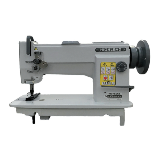
HIGHLEAD GC0618-1 Manuel d'instruction Catalogue des pièces - Page 11
Parcourez en ligne ou téléchargez le pdf Manuel d'instruction Catalogue des pièces pour {nom_de_la_catégorie} HIGHLEAD GC0618-1. HIGHLEAD GC0618-1 13 pages. Heavy duty compound feed lockstitch sewing machine

20 TIMING OF THE VIBRATING PRESSER FOOT
This is the normal liming when turn the balance wheel toward you, after lowering the presser bar
lifter, the vibrating presser foot should reach the feed dog earlier than the needle eye comes to,
and when the needle raises, the vibrating presser foot should leave the feed dog after the needle
eye has left the feeder. This is due the reason that the vibrating presser foot must lightly hold the
goods while the needle is passing the goods for avoiding irregular stitches. To adjust this, set the
lift of the alternating presser feet to equal, loosen the two screws 4 (Fig 20) and adjust the rotating
position of the cam 5 (Fig 20) faster or slower as may be desired, and tighten the screws.
21 ADJUSTMENT OF THE CLEARANCE BETWEEN
FEED FORKED CONNECTION A D FEED FORK
COLLAR (Figs 15, 16)
Incorrect clearance between the fork 8 of feed forked connection and feed fork collar 9 will bring
irregular stitch length or overheating etc. To adjust this, open the cover plate. Remove the cover
plate and the oil reservoir. To increase the clearance, loosen the screw and turn the screw to left or
counter-clockwise. This adjustment should be done with turning the balance wheel toward you to
get correct clearance. Upon completion of adjustment, tighten the screw which is loosened to touch
the feed fork.
22 ADJUSTING THE THREAD
CONTROLLER
SPRING (Fig 21)
Normally, the thread controller spring 1 should hold
slack of the upper thread until the needle reaches to the
goods, and it should pause while raising of the needle
and passing of the upper thread through the bobbin
case.
1 ) For more controller action on the thread: Loosen
the stop screw 2, move the stop to the right (For
less action, move to the left). Tighten the screw.
2 ) To adjust the tension spring: Loosen the serrated
nut 4 and the screw 5. Turn the tension stud 6
slightly to the left to strengthen the tension (to lighten the tension, turn to the right) with a
screwdriver. Tighten the screw and nut upon completion of adjustment.
1
6
3
Fig 21
Fig 22
Adjusting tool
4
5
2
