COPLAR LTA-LG-01 Manuel de l'opérateur - Page 8
Parcourez en ligne ou téléchargez le pdf Manuel de l'opérateur pour {nom_de_la_catégorie} COPLAR LTA-LG-01. COPLAR LTA-LG-01 11 pages. Line trimmer attachment
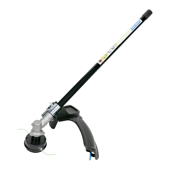
JOINING THE POWER HEAD TO THE STRAIGHT SHFT TRIMMER TTACHENT
See Figure 2.
WARNING:
Never attach or adjust any attachment while power head is running. Always Stop the unit and remove the spark
plug wire or disconnect from the power supply. Failure to heed this warning can cause serious personal injury.
The straight shaft trimmer attachment connects to the power head by means of a coupler device.
1. Loosen the knob on the coupler of the power head shaft and remove the end cap from the
attachment shaft .
2. Push in the button located on the straight shaft trimmer attachment shaft. Align the button with the
guide recess on the power head coupler and slide the two shafts together. Rotate the straight shaft
trimmer attachment shaft until the button locks into the positioning hole.
NOTE: If the button does not release completely in the positioning hole, the shafts are not locked
into place. Slightly rotate from side to side to side until the button is locked into place.
3. Tighten the knob securely.
WARNING:
Be certain the knob is fully tightened before operating equipment; check it periodically for tightness during use
to avoid serious injury or product damage.
REMOVING THE ATTACHMENT FROM THE POWER HEAD
For removing or changing the attachment:
1. Loosen the knob.
2. Push in the button and twist the shafts to remove and separate ends.
TO ATTACH THE STRAIGHT SHAFT GRASS DEFLECTOR See Figure 3.
1. Remove the wing screw from the grass deflector.
2. Insert the tab on the mounting bracket in the slot on the grass deflector.
3. Align the screw hole in the mounting bracket with the screw hole in the grass deflector.
4. Insert the wing screw through the mounting bracket and
5. Tighten the wing screw securely.
- 8 -
A
SSEMBLY