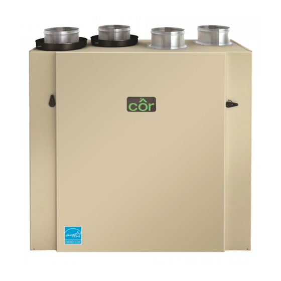
Cor HRVCRSVU1157 Manuel d'instructions d'installation - Page 4
Parcourez en ligne ou téléchargez le pdf Manuel d'instructions d'installation pour {nom_de_la_catégorie} Cor HRVCRSVU1157. Cor HRVCRSVU1157 17 pages. Heat recovery ventilator

TYPICAL INSTALLATIONS
Use the following illustrations as guidelines to help you decide on
how the unit will be installed. All the units should be hung from
the joists.
If required, bathroom fans and a range hood may be used to
exhaust stale air. Also, for homes with more than one level, we
recommend one exhaust register at the highest level.
There are 3 installation methods: Fully ducted, Central Draw Point
and Simplified Installation.
NOTE: An electrical outlet has to be available within 3- ft of the
unit.
Fully Ducted System (Primarily for homes with
radiant hot water or electric baseboard heat.)
Stale air coming from the registers located at the highest level of
the house is exhausted to the outside. Fresh air from outside is
filtered and supplied by the register located in the lowest liveable
level.
Homes with more than one level require at least one exhaust
register at the highest level.
See Fig. 4.
Fig. 4 - Fully ducted system
Central Draw Point (Connection to a forced air
system.)
Stale air coming from the registers located at the highest level of
the house is exhausted to the outside. Fresh air from outside is
filtered and supplied to the return (plenum) or the supply duct of
the forced air unit. See Fig. 5.
For this type of installation, it is not essential that the forced air
system blower runs when the unit is in operation, but it is
recommended.
NOTE: Home with multiple forced air systems should have one
unit on each system.
Fig. 5 - Central Draw Point
Simplified Installation (Connection to a forced air
system.)
Stale air is exhausted to the outside. Fresh air from outside is
filtered and supplied to the return (plenum) or the supply duct of
the forced air unit. See Fig. 6.
To avoid cross- contamination and achieve the highest efficiencies,
the forced air system blower must always be ON.
NOTE: Homes with multiple forced air systems should have one
unit on each system.
Inspect the contents of the box
Inspect the exterior of the unit for shipping damage. Ensure that
there is no damage to the door, ports, power cord, etc.
Unit Door
HRVCRSVU1157 has one door. The unit door can be relocated on
A11193
the back of the unit. This can be helpful to optimize duct
configuration while keeping access for unit maintenance. To
change door location, follow these steps (see Fig. 7):
A. Remove both door lower mechanical screws no. 8- 32 x 1- in
(1) and set aside.
B. Open (2) and lift out the door (3).
To remove unit back panel, repeat steps A and B, but instead of
removing 2 mechanical screws, there are 4 metal screws to be
removed. Hang the door to the back of the unit and secure it by
tightening its both lower mechanical screws. Hang back panel to
the front of the unit and secure it by tightening its four metal
screws.
A
1
A11194
4
Fig. 6 - Simplified Installation
INSTALLATION
B
3
Fig. 7 - Hanging the door
A11195
2
A11196
