Dynojet Power commander GSXR750 Manuel d'installation - Page 4
Parcourez en ligne ou téléchargez le pdf Manuel d'installation pour {nom_de_la_catégorie} Dynojet Power commander GSXR750. Dynojet Power commander GSXR750 4 pages. Power commander v input accessory guide
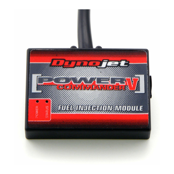
FIG.D
20-037
www.powercommander.com
7
Using the supplied Velcro, secure the PCV module in the tail section (Fig. D).
Use the supplied alcohol swab to clean the surface area prior to applying the
Velcro.
Make sure all wiring is routed properly and also free and clear of any hot or
moving parts.
8
Lower and bolt down the front of the fuel tank.
Note: When lowering the fuel tank, make sure the fuel line and PCV wiring
harness do not get kinked or pinched at the frame support. If this happens, the
bike might not run properly.
9
Reinstall the main seat and passenger seat.
NOTE: Suzuki made a mid year change in 2001 and it is possible that this
unit will NOT match your connector. If this is the case then you will need part
#20-038
Optional Inputs:
Speed input - PINK wire on BLACK 3-pin connector from speed sensor on
the countershaft sprocket cover (BLACK/RED, BLACK/WHITE, PINK)
Temperature input - BLACK/BROWN wire of temp sensor at the rear of
the engine.
12v source for Auto-tune - BROWN wire of taillight connector
2000-2001 Suzuki GSXR750 - PCV - 4