Adeunis RF BINDER CONNECTOR Manuel de démarrage rapide - Page 12
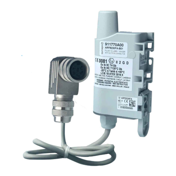
Parcourez en ligne ou téléchargez le pdf Manuel de démarrage rapide pour {nom_de_la_catégorie} Adeunis RF BINDER CONNECTOR. Adeunis RF BINDER CONNECTOR 12 pages. Pulse atex transceiver combined with a 6-pin binder connector

BINDER Connector - Guide utilisateur / User guide version V1.0.0
BINDER Connector - Guide utilisateur / User guide version V1.0.0
Binder connector - Package IoT - Quick start guide 1.0.0
1.4.2 Data frame
This frame (0x46) is transmitted every 1440 min so once a day.
0
Code
0x46
FR
0x46
Its size is of 10 bytes.
Description of the frame:
•
Bytes 2 to 5: counter value for channel A when transmitting the frame
•
Bytes 6 to 9: counter value for channel B when transmitting the frame
EN
In the example in grey this gives:
•
Bytes 2 to 5 : counter channel A = 0x00015C4F so 89,167 pulses
•
Bytes 6 to 9 : counter channel B = 0x0000F74A so 63,306 pulses
1.5. Change of settings
The package is proposed with defaults settings explained above. For any change on the transceiver configuration, refer to the PULSE ATEX User
Guide available on our website
1.6. Technical specification
1.6.1 PULSE ATEX transceiver
For any information on the technical specifications of the PULSE ATEX transceiver refer to the PULSE ATEX User Guide available on-line:
https://www.adeunis.com/en/produit/pulse-atex-3/
1.6.2 Binder connector
Information on the Binder connector provided the manufacturer:
Description : Contacts: 6 DIN, angled female connector, shieldable, passage for the wires 4 – 6 mm, silver contacts, with UL approval
Reference of the product : 99 5122 75 06
Main features
Connector design
Locking the connector
Connexion
Upper limit temperature
Lower limit temperature
Electrical specifications
Rated current (40°C)
Nominal voltage
Nominal shock voltage
Surge category
Group of insulating material
Volume resistivity
Insulation resistance
EMC compliance
Protection rating
1
Status
Cf Status
0xA3
https://www.adeunis.com/en/produit/pulse-atex-3/
Angled female connector
Bolted
Welding
95
-30
5
250
1500
I
III
≤ 5
10
≥ 10
shieldable
IP67
2 to 5
PAYLOAD
Counter - channel A
0x00015C4F
Unit
-
-
-
°C
°C
Unit
A
V
V
-
-
mΩ
Ω
-
-
6 to 9
Counter - channel B
0x0000F74A
12 of 12
