Jaga JRT-100 Installation, réglages et utilisation - Page 13
Parcourez en ligne ou téléchargez le pdf Installation, réglages et utilisation pour {nom_de_la_catégorie} Jaga JRT-100. Jaga JRT-100 16 pages.
Également pour Jaga JRT-100 : Manuel d'installation, de configuration et d'utilisation (4 pages), Manuel d'installation, de configuration et d'utilisation (4 pages), Installation, réglages et utilisation (17 pages), Installation, réglages et utilisation (4 pages)
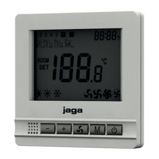
JAGA ROOM THERMOSTAT JRT-100
INSTALLATION , SETTINGS & USE
Important info : The unit must be installed by a certified installer in accordance with the installation instructions and the local building codes. Please
follow this instruction manual and file it somewhere safe! The unit must always be accessible for maintenance and inspection. . Jaga n.v. cannot be held
liable for damage due to non-compliance with this manual.
PRODUCT DESCRIPTION
– 2-pipe and 4-pipe connection :
– 4-pipe connection : Heating / Cooling / Auto-change-over
– 2-pipe connection : Heating / Cooling
– automatic or manual fan speed control
– mounting on mounting box with screws
– programmable time zones (5+1+1): Monday - Friday (1-5), Saturday (6), Sunday (7)
– 0-10V exit
– valve control with 24V AC / DC thermoelectric motor
– possibility to run the fan once the"set point" has been reached (manual operation)
TECHNICAL DATA
POWER SUPPLY
POWER CONSUMPTION
SETTING RANGE
AMBIENT TEMPERATURE
RELATIVE HUMIDITY
BACK-LIGHT
SENSOR
ACCURACY
SAFETY CLASS
HOUSING
DIMENSIONS
8.6
8.6
M
CE MARK
The CE mark indicates hat this device meets the basic requirements of the directive on:
• EN 61000-6-3:2007+A1:2011
• EN 61000-3-2:2006+A1:2009+A2:2009
• EN 61000-3-3:2008
• EN 61000-6-1:2007
24V AC/DC
200 mA
+10 ... +40°C
0 ... +40°C
85% max
Blue
NTC 10K, 3950 ohm at 25 ° C
+ 1°C (+0.5°C)
IP30
ABS with UL94-5 flame retardant plastic
6
JRT-100
DEVICE INSTALLATION GUIDELINES
Install the room thermostat at approximately 1.5
m above the floor against an interior wall and
opposite the heating source if possible. Avoid
the outer walls, draft coming from the windows
and doors, direct sunlight and other heat sour-
ces such as TVs, wall or table lamps, fire places,
heating pipes, etc. Ensure that the locking
mechanism on the bottom of the thermostat is
1.4 3.4
easily accessible.
Mount the JRT.100 Room thermostat in a flush
mounting box with screw holes at a 60 cm
distance from the center. Minimum depth 45mm,
(the depth depends on the wiring). The internal
dimensions of the box should be at least Ø60mm
or 50x50mm.
MANUAL
www.jaga.com/downloads/
Briza/Manual_JRT100.pdf
/ 8751.050012
1.5 m
4.6
6
EN
1.5