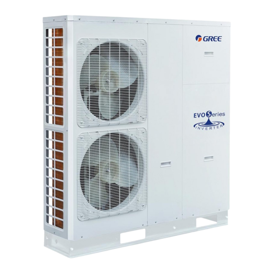
Gree HLR8Pd/Na-K Manuel d'installation de l'unité - Page 13
Parcourez en ligne ou téléchargez le pdf Manuel d'installation de l'unité pour {nom_de_la_catégorie} Gree HLR8Pd/Na-K. Gree HLR8Pd/Na-K 18 pages. Mini chiller

WARING!
Normal Open type should be connected to wire (ON) and wire (N)for valve closing in cooling mode.
①
Normal Closed type should be connected to wire (OFF) and wire (N)for valve closing in cooling mode.
②
(ON) : Line signal (for Normal Open type) from PCB to 2-way valve
(OFF) : Line signal (for Normal Closed type) from PCB to 2-way valve
(N) : Neutral signal from PCB to 2-way valve
The 2-way value 2 is reserved without any control program. At the field installation, it should be wired at the
terminal board of the 2-way valve 1.
4.9 Wired Controller
Wired controller wiring guidance:
4.10 Wiring of Other Auxiliary Heat Sources
Other auxiliary heat sources are allowed for the equipment and controlled in such a way that the mainboard
will output 230V when outdoor temperature is lower than the set point for startup of the auxiliary heat source.
4.11 Wiring of the Gate-Controller
If there is gate control function,installation guide follow as:
(1) HLR8Pd/Na-K, HLR10Pd/Na-K
(2) HLR12Pd/Na-M, HLR14Pd/Na-M
13
14
XT2
N
Other Thermal
XT3
1
2
Gate-Controller
XT4
5
6
Gate-Controller
11
Unit Installation
